Some time last year, Mats Engstrom shared his PHP script for generating commands to move components in CadSoft Eagle to form a perfect circle. If you look at the screenshot, it’s mainly made up of MOVE and ROTATE commands – relatively easy.
Eagle has what it calls user language programs (ULPs) for doing some simple scripting with the ability to display a dialog for user input. I decided to try my hand at creating a ULP that creates these circular layouts. The main advantage of using a ULP is that it has access to your board layout, saving you from some typing. You can also easily iterate through different parameters quickly and without hassle.
I shall illustrate briefly how this circular layout ULP can be used for doing various kinds of layout, with help from some open-source projects with Eagle CAD files.
Ringo3 Clock
The most common use for a circular layout is in clocks. Conveniently, Mats has a project called Ringo3. For photos of the PCB and assembled clock, see this Dangerous Prototypes forum topic.
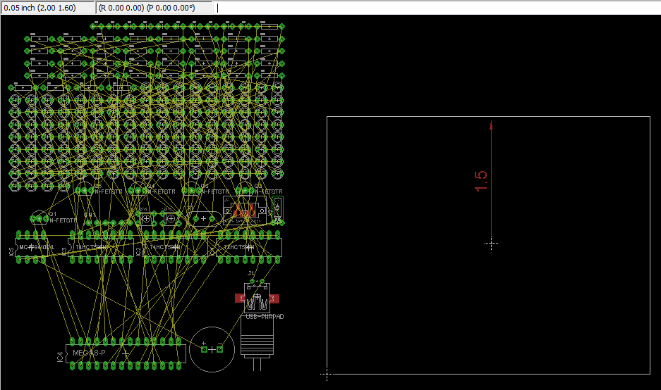
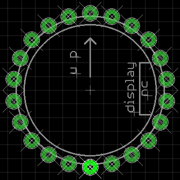
Delete the existing board (.brd) file to start with an empty PCB created from the schematic. We shall take (2.00, 1.60) to be the centre of the circle, as shown. Eagle 6 introduced a dimensioning tool, used here to show the radius of the circle (1.5″) – handy but not a must.
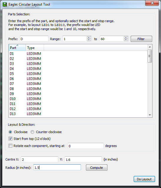
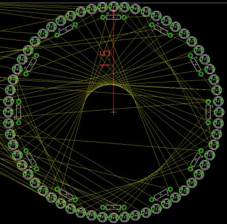
The circular layout ULP has 3 main sections: (i) parts selection, (ii) layout options, and (iii) circle centre point & radius. For parts, enter D for prefix and 1 to 60 and click the Filter button to select components D1 – D60 for layout. The handy table shows you the currently selected list of components. Enter 2 and 1.6 for the circle centre X, Y values that have been identified. The radius has been marked by the dimensioning tool as 1.5. The layout direction is “Clockwise” and we want to place D1 at the top “12 o’clock” position. Click the Do Layout button, and OK to start the layout.
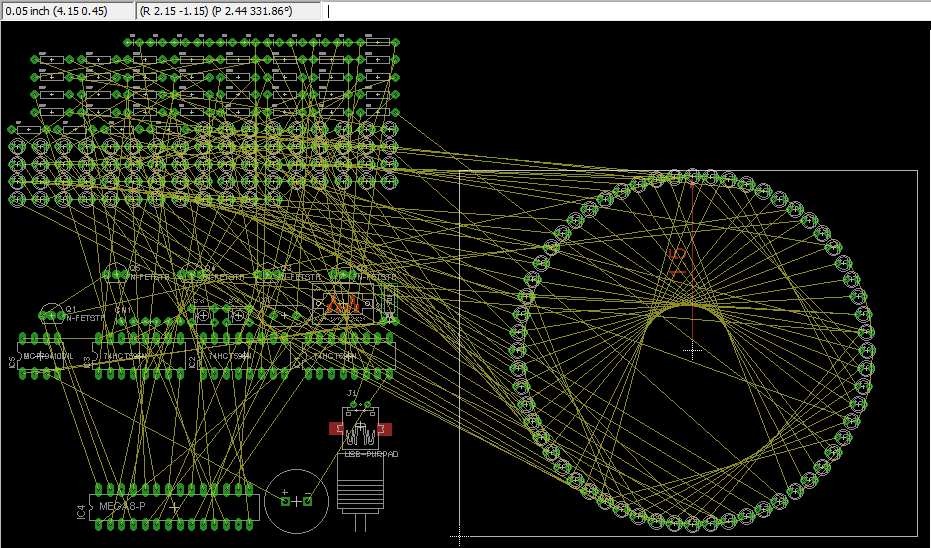
You should see the components move into place as shown in the next figure.
If you make a mistake, you can always just hit Undo or hold down Ctrl+Z until all the components were back at their original positions.
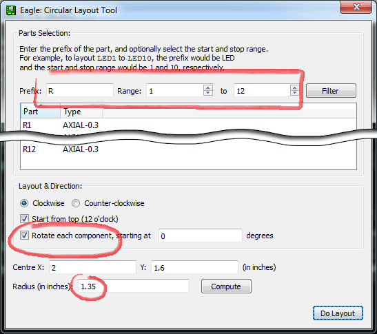
You might also want to place the resistors close to the LEDs, so we shall try that next. From the schematic, we can see that every group of 5 LEDs share 1 resistor, so we shall layout R1 – R12 for these LEDs. All the settings will be the same as before, but we want the radius to be smaller (1.35" this time). We shall check the “Rotate each component” option, but leave the angle offset box at 0 degrees (we’ll talk about that shortly).
You should see the following result.
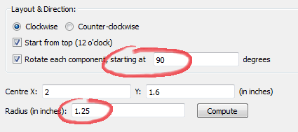
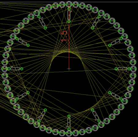
If instead we want the resistors to point outwards (or inwards), the angle offset should be changed to 90 degrees to orient R1 in the 90-degree position. Since the resistors now take up more space, we should also reduce the radius accordingly to 1.25".
This is the basic circular layout, but wait, there’s more!
Ice Tube Clock
Adafruit carries what it calls the Ice Tube Clock. The circular layout ULP works for Eagle footprints too. You can see that the footprint for the tube isn’t a perfect circle – a circle was drawn to (I guess) guide the placement of the pads (or holes, rather), but it also shows that the pads are not equidistant from the circle.
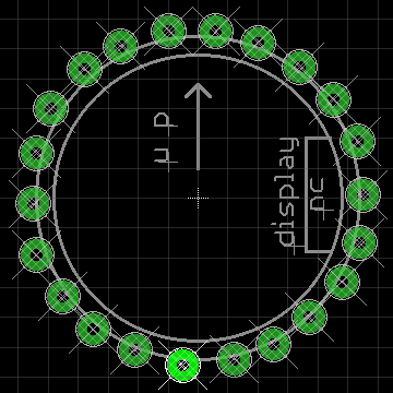
In this case, we want as little change as possible to the layout. By unchecking the “Start from top” option, the ULP will calculate the position of the pads as usual, but will now try to locate the position closest to the first pad and start there. This option tells the ULP that you have already roughly placed the first component and you want it to start there. At this point, you can also hit the Compute button for the “Radius” field to calculate the distance of the first component from the circle centre. Note that for footprints, Eagle would prefer your part to be around the center point (0, 0), so you didn’t have to fill in the circle centre X, Y coordinates.
Notice the new position of pin #1. To highlight the pin 1, just type SHOW 1 in the command bar, just above the layout window. You should see the pin highlighted, like in the screenshots.
If you think the circle is too small, you can just move pin 1 further outwards, launch the circular layout ULP, and hit the “Calculate” button to detect the new radius, then hit the Do Layout button to make the circle larger.
Download, Use, Modify
These are the scenarios which I use the circular layout for and there may be others I haven’t thought of, or needed. Feel free to use this ULP for laying out your boards, or modifying it to suit your needs.
To start using it, you can download the ULP from my Bitbucket GitHub repository.

Hello irq5.io,
the circle layout ULP Eagle is also works on version 5.11 for a PPC Mac with OSX 10.5.8?
Which circular ULP I can use?
Thanks,
Bruno
Hi Bruno, I believe the ULP will work for Eagle 5.11 as well (although I have not tested it).
You will need to download the ULP from the link provided above. In EAGLE (board editor), click on
File > Run ULP...and select the ULP file that you have downloaded.I did as you wrote, but when I launch the ULP it answers:
“/ Volumes/APPLICAZIONI/11 EAGLE / ulp / circular-layout.ulp (84):
syntax error ”
then displays a window with all codes.
Can I send you a file with figures?
I schools for my English translated by google.
Greetings.
I’ve just tested it on EAGLE 5.11 and I see the same error. I have fixed it and the new version should work fine now. 🙂
VERY BIG!
The application now works, bat:
– It does not work in mm.?
– Why in the box: “Range:” and “to” is the default the number “-1”?
Thanks, Thanks, Thanks.
1) The ULP currently only supports inches. Maybe when I have time I might make it support more units like mm, but for now you will need to manually convert the units.
2) By default the range is -1 to -1, which selects all components. You can play around with the numbers and press the “Filter” button to see its effects.
Good.
The Italian Forum of Eagle was unable to give me an answer on this ULP. I tried it for years.
In my new forum I gave you the link to download your ULP.
I am very happy.
Thank you.
Bruno
Hello Darrel, I have posted your ULP “Circular Layout ULP for Eagle” in my forum and it has been very much appreciated.
Thank you,
Bruno.
Thanks Bruno! I’m glad you found it useful.
Hi,
good job! But I have error with Eagle 5.4:
…/circular-layout.ulp(38):
Unknown identifier ‘strxstr’
This ULP could be very useful for me, but it don’t work for me.
Hi Marvin, I realised strxstr was introduced in version 5.5. I have made some changes which will hopefully work on v5.4. Give it a try and let me know how it goes. Thanks!
Thank you! Now it’s working well. I tried component-array.ulp (downloaded from cadsoftusa.com). It can place components in array or circular. In circular mode it have a variable angle for placing. So you can place LEDs in 90° circular. And it can rotate each component automatically.
One think can not do both ULPs. I need to start at variable angle. When I have quad/half… circular PCB, I need to start not at zero angle, because in this zero angle is PCB edge. Mostly I need start at half angle of main angle.
When I do 90 degree angle placing in component-array.ulp – first and last component do not meet at right angles – one last LED is missing to have right angle, but the number of components is correct – so it has bad dividing of variable angle. When I’m placing components in 90 degree, first start in 3 o’clock, but last is not at 12 o’clock, but in 1 o’clock for example. This might solve starting angle for first LED (in half angle of main angle) for me. First and last components will not have correct angle, but the correct angle will be PCB! Do you understand my thoughts?
Sorry for my bad English…
Hi Marvin, I tested it and I understand what you mean. It is currently done this way because it is easier to assume a full circle and calculate the positions based on that. If you play with the formulas, it’s definitely possible to get the angles that you want.
If I had time and sufficient interest, I might probably add that feature into the ULP.
Hi Darell, I found that Eagle 5.x/6.x has ULP named cmd-draw.ulp. With this ULP I can make full/half/quater/any cicle board and any linear board with auto placing component by the way. I has more features.
When I will have any time, I’ll try to modify this ULP.
Hi Marvin, thanks for sharing! I didn’t know about those ULPs before. I will play around with them when I get the time.
Darrell Is there any possibility you could help me out with a ULP that does something similar to this one, I am wanting to place an x and y coordinate in parts on the schematic and have them auto magically position correctly by those coordinates in the PCB when the ULP is run – for position holes and rebuilding component placement if the board outline changes.
I am trying to get the hang of this ULP language stuff but without an IDE or the ability to get some form of meaningful command feedback from the layout editor I feel like I am banging my head against a brick wall.
Have done a lot of programming in my life but feel a bit frustrated with this one and would appreciate any help you could provide.
Hi Chasse, for such tasks I would recommend using another language to generate a script with
MOVEcommands, then running the script in Eagle. This approach is used by Mats (linked in the article). Or you might find the PyEagle project easier to use if you prefer Python as your programming language.Unless the layout is consistent across boards (such as placement in a circle), I would recommend against making a ULP specially for it. But who am I to dissuade you in your quest? 🙂
It’s taken me about 3 days but I now have a ULP to take the locations and angles of components already placed on a board and transfer them to attributes within the components of the schematic. I also have nearly finished a ULP to take the attributes and move the appropriate components to the locations on a newly drawn board, it wasn’t easy without an IDE and debugging to text files but it is now working and in active use. I’m producing a motherboard and needed to determine from having the components bang them selves on to the board what the smallest board was that would fit taking into account fitting of expansion headers, mounting holes and that sort of thing to make sure stuff fits mechanically.
Thanks for the recommendation though I’ll look into it for any further scripting.
Bloody wonderful! As someone who has been manually laying out circles of LEDs for a street lighting project in our village (in DakLak Province, Central Highlands, VietNam)(Non-commercial use in the Ede and Hmong reservations) because Eagle’s CMD-Draw didn’t function properly, your program takes the prize.
Within minutes of loading it, I was busy churning out layouts with perfect circles! Not sure what all the commands are for, yet, but a little fiddling with the settings gets the job done.
Now what we need is a better way to group things – drawing lines around an area seems a little 1990’s.
Thanks again.
Just stumbled across this ULP. Does anyone by chance has still a copy? The repo link unfortunatly does not work anymore.
Apologies. I will find the time to restore and/or migrate the code repository and update this page accordingly. Please check back here in a day. Thanks!