Now is probably a good time to mention that I have a paper shredder. When I was shopping for a shredder, the basic requirement is that it must be relatively “secure”. Straight cut shredders (that produce long straight strips) are definitely not secure.
Ultimately I settled on the CARL DS-3000 personal paper shredder. The DS-3000 is a cross-cut shredder which produces “particles” no larger than 2mm x 4.5mm and this meets DIN security level 4. These days, the NSA mandates 1mm x 5mm “particles” for classified documents.
At this point, it’s probably helpful to show you what my shredder bin looks like:

From the particles, you can make out various truncated words such as “A/C”, “exp” and the number “5”, but it’s almost impossible to reconstruct any bank balances or personal information from it.
This particular model was the right balance between my budget and the level of security. Plus, the shredder is compact enough to sit on your desk. I bought it in 2009 and I use it every couple of months when I have accumulated enough material that needs to be destroyed.
I was in the middle of shredding papers when it suddenly stopped working. Now the shredder does not respond when I stick paper into its slot. The LED indicator looks dimmer than usual when it is turned on.
But I’m not ready to give up on it just yet…
Features
The shredder activates when the input sensor detects paper at the input. It also has a safety feature that ensures it only works when the paper bin is closed. Additionally, it has a sensor to detect the waste level in the bin. If the bin is too full, the shredder refuses to work.
The shredder can also be momentarily placed into reverse mode where it spits the paper back out. This is useful where there’s a paper jam. While I don’t abuse the shredder, putting it in reverse still spits some bits of paper out occasionally.
Disassembly & Reverse-engineering
Shredders are typically self-contained units and fit on top of a waste bin. It is like that for a heavy-duty shredder used in my office and this unit is no different, just smaller. A couple of screws hold the top unit to the waste bin, and after lifting out the unit, just undo the remaining screws to access the inside.
Inside, there is a circuit board that activates (or not) the shredder based on the various sensors. It has various modular connectors so the sensors and motor can be detached. The board was most probably made in China, due to the selection of parts (SongLe for the relay and Tenta for the dropper cap).
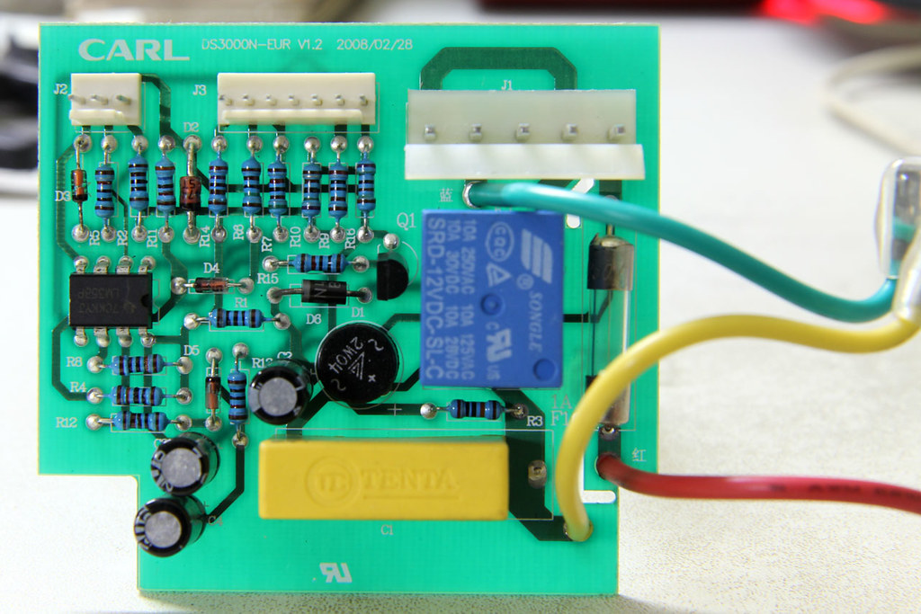
I had to reverse-engineer the circuit first to get a high-level overview of how the device worked. This is what I came up with, the schematic split into various parts, in order from top to bottom: (1) DC step-down, (2) motor driver, (3) paper feed sensor stage and (4) bin full sensor stage.
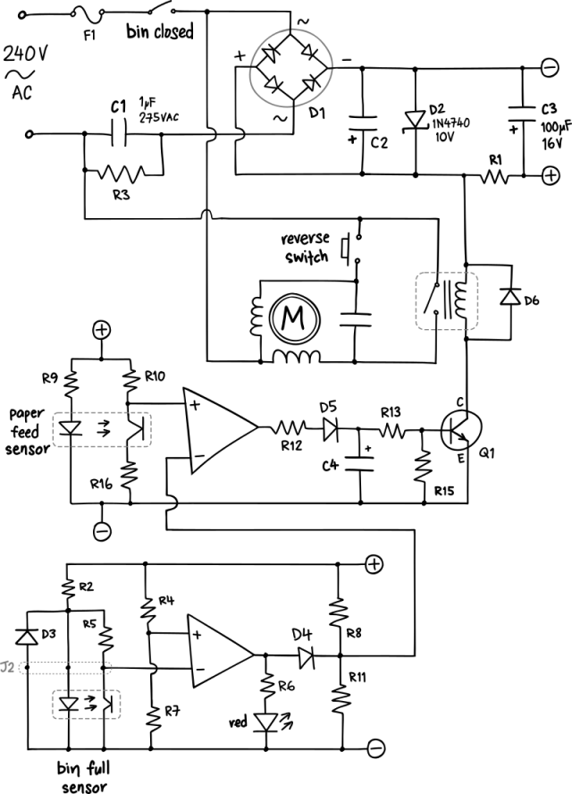
I have always found it interesting to see how things work, or how they are designed. The motor needs to run in both forward and reverse directions, so they used a permanent-split capacitor motor, which has 2 sets of windings and a capacitor wired in series with one winding would cause a phase shift and thus determines the direction of rotation. An LM358 (dual op-amp) is used as comparators for the bin full sensor and the paper feed sensor. There are no adjustment pots, so the bin level (distance) sensor should be relatively consistent. The paper feed sensor output keeps the relay on for a few seconds, through a peak detector type circuit formed by D5, C4 and R13. C4 and R13 forms an RC delay circuit, keeping the relay on, while D5 forces the capacitor to be discharged through the base of Q1. To save cost (by buying in bulk), they used the same capacitor for C2, C3 and C4, even if it may cause some minor problems (described later).
The indicator LED was dim, so I suspected some type of regulation problem. The most common of such problems are bloated capacitors, but these looked OK. When the switch when depressed into “reverse” position, the motor still worked so that was not the problem. In the worst case it could have been hard-wired to bypass the control circuit and function without all the sensors.
Voltage regulation in this circuit was done in 2 stages. This design is quite common but can only be used within an enclosed appliance (no metallic parts exposed to the user) due to the lack of an isolation transformer.
- 240V AC to DC through a capacitive dropper
C1and rectifier bridgeD1 - finer regulation to 10V using zener diode
D2and capacitorC2
The easiest, least invasive method to check which component is not working is to remove the bridge rectifier D1. I then attached a 12V DC unregulated adapter to power the rest of the circuit, across the zener diode D2. It turns out that everything is working, the sensors are responding normally and energizing the relay as expected, which means that stage 2 voltage regulation is working fine.
The Repair
I proceeded to order replacement parts for both the dropper capacitor C1 and the bridge rectifier D1 from element14, my favourite online store for electronic parts1. While it is quite unlikely that the bridge rectifier would fail, I still ordered a replacement anyway. A more likely candidate would be the dropper capacitor C1 (the yellow box capacitor). It is rated for 275VAC, within a 15% margin of 240V, but has no in-rush current limiting resistor.
Apparently 2W04 seems to be a rather common bridge rectifier, and a Multicomp branded part was easily and cheaply available. The form factor of box capacitors are standard, but this Tenta capacitor is shorter than most. They used the MINI MEX-X2 series, which has a 19mm height compared to the MEX-X2 series which is 20mm. In the end I settled for a Wurth Elektronik capacitor, but rated for 310VAC instead of 275VAC. It has a height of 20mm, which is already the maximum allowable height as it will hit a screw that holds the motor’s capacitor when the PCB is re-seated.
The replacement parts are as follows:
D1bridge rectifier: Multicomp 2W04MGC1dropper capacitor: Wurth Elektronik WCAP-FTXX series, 1uF 310VAC
The bridge rectifier arrived first and as expected, replacing that didn’t help. The box capacitor came the next day, and replacing capacitor C1 fixed the voltage regulation (and thus, the shredder).
The cost of the replacement parts add up to be less than 2% of the original cost of the shredder. My adventure to fix the shredder and sense of achievement? Priceless.
It’s Not a Bug, It’s a Feature
When I first got the shredder, I realized that when it was working (shredding paper), the LED indicator flashed red and I thought “hey cool, they designed it to indicate when the shredder was busy.”

But looking at the circuit diagram, there was no feedback from the motor — it was driven through a relay. It turns out that the flashing was caused when the motor was under load and that probably affects the comparator inputs to the “bin full” sensor. The shredder keeps going because of the RC delay circuit; capacitor C4 is still being discharged into the transistor, causing the relay (and motor) to stay energized.
It’s interesting that as an engineer, you know it’s a problem that needs to be fixed, but the designers probably said “no, it’s a feature” and that’s what we are seeing now.
- I was not paid to say this, although it would be nice if they did ;-) ↩

please leave the value of each resistance..thanks…
You can read the resistance values from the photo, or use nominal values.
the color doesn’t clear..
Then you will have to use nominal values.
thanks..:)
Thanks so much for sharing this work. Your efforts are appreciated!