I had the opportunity to collaborate with some NUS students to design the electronic badge for their X-CTF event this year.
The purpose of the badge was to inspire more people to take an interest in hardware hacking, or to get them started on electronics. With so much hype on the Internet-of-Things (IoT) these days, what better idea than to let participants take home their very own IoT device. The super low cost WiFi chip, Expressif’s ESP8266, made this possible. We also wanted it to be shaped like a gaming device, with a D-pad and an LCD.
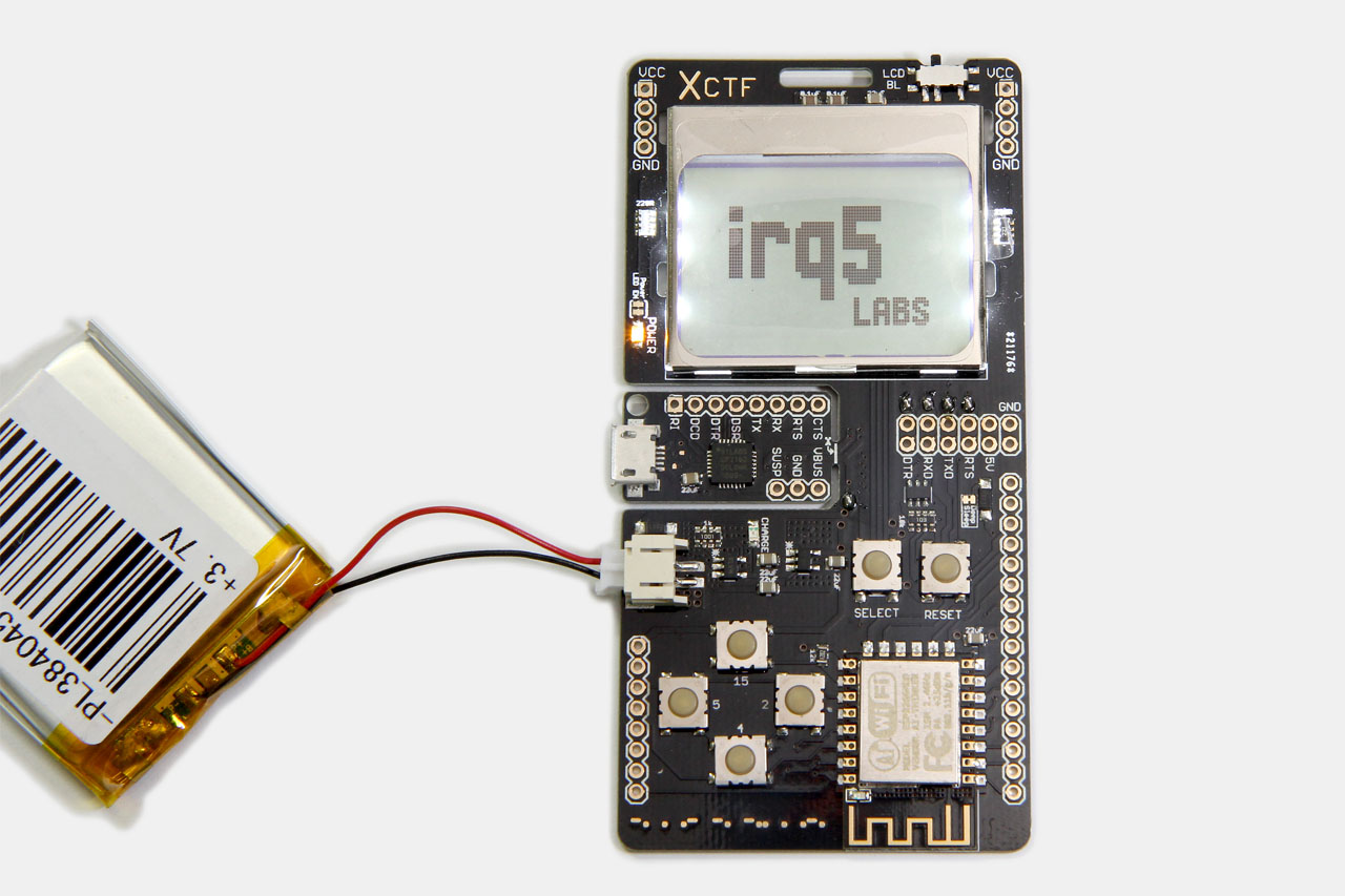
You can see the final badge design above: a ESP8266-based board with a backlit monochrome Nokia LCD, D-pad and a SELECT button. Powered by a lithium-ion battery, charged via the USB port, which also provides a serial connection to the ESP8266.
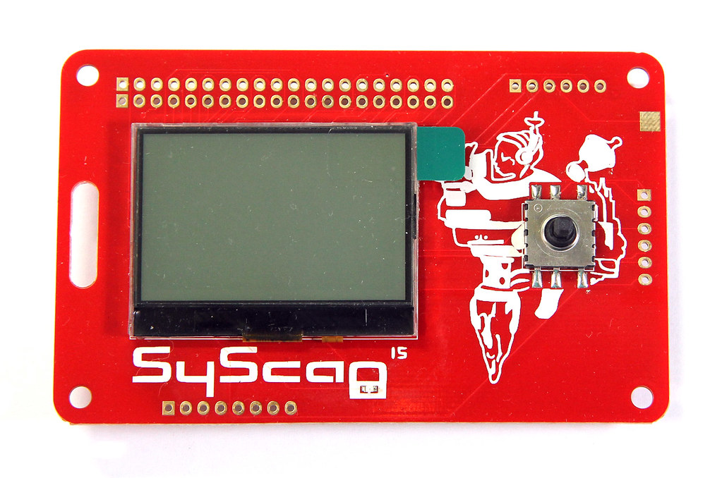
I was inspired by the SyScan 2015 badge. It was so simple and spartan: a monochrome LCD, an LED, a 5-way joystick switch and a 32-bit ARM processor (on the back). As the regulator was built-in and it runs all the way down to 2.4V, there was no need for an external regulator.
LCD Display
Most of the low cost LCDs either hot bar soldered onto the board or a special fine-pitched connector, and subsequently, neither of these had a solution to be fastened to the board. For example, the SyScan badge used double-sided tape to secure the LCD to the board.
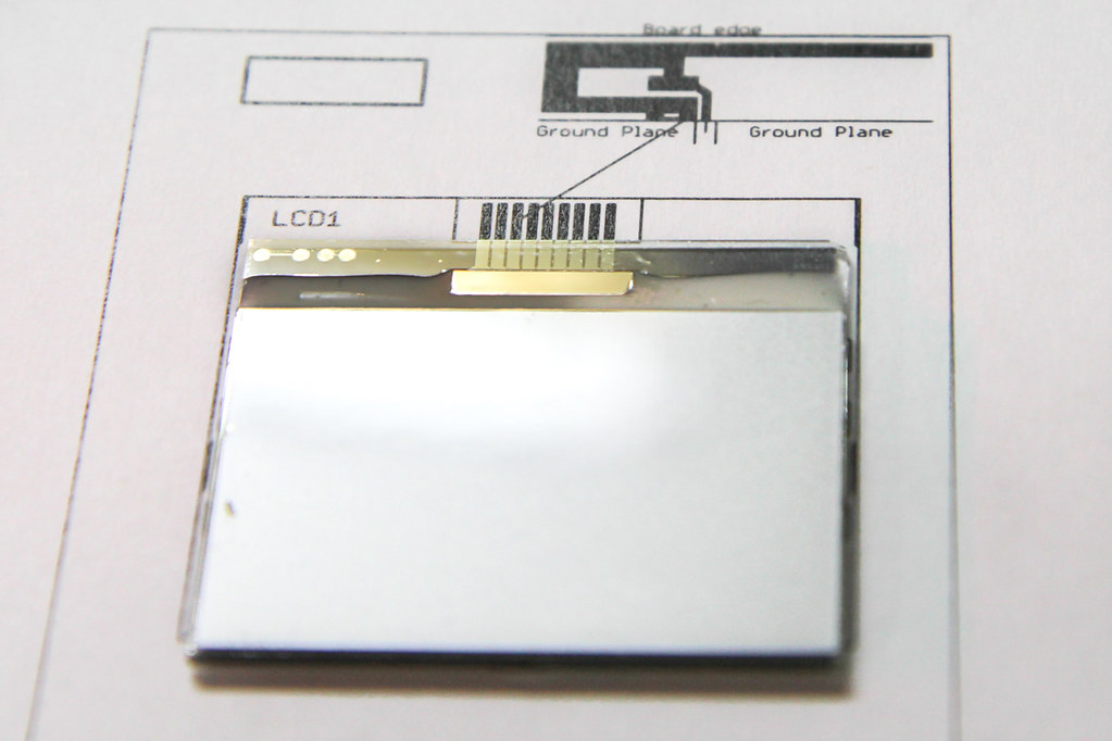
Nokia LCD screens were abundantly available and cheap. These LCDs have the part number LPH-7366 printed on the back, or are sometimes referred to as PCD8544, which is the LCD driver embedded into the display. They also have another advantage of being easy to assemble because the LCD is enclosed in a metal frame with retaining clips. The only thing needed was to get the PCB footprint right.
We started off from a user-contributed footprint on the Cadsoft site, but slowly tweaked it because of its overly-long zebra connector traces and the lack of holes for the retaining clips.
The LCD has a zebra strip connector that mates the copper traces on the PCB with the conductors on the glass. There doesn’t seem to be any datasheets on the LPH-7366 that we can consult for dimensions but we can try to match it up under light at a certain angle to see if the copper widths should be made wider or thinner. You can see the PCD8544 display driver embedded on the glass of the LCD, just beneath the connector here:
There doesn’t seem to be much details online about using these bare screens directly in your project (without the breakout board). There are quite a few sites that tell you how to wire it up, but no tested and open-sourced project with CAD files. If you are interested in doing this as well, you’ll be happy to know that we are open-sourcing this badge.
Buttons
Initially I wanted a 5-way joystick, like the SyScan badge. I bought one seemingly popular model from AliExpress, but found it too small compared to the SyScan one.
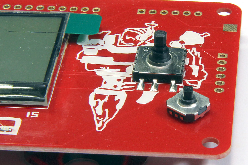
I also bought the very common type of tactile switches but surface mount instead of through-hole. It turns out those required quite a bit of force to actuate (it feels hard to depress). These are quite common problems because parts sold on AliExpress usually lack datasheets or specifications. If you look hard enough though, you might be lucky to find a seller who will include a screenshot of the datasheet in their item description.
Instead, Jeremias found these very nice and big tactile buttons – the Panasonic EVQQWN03W. We ended up using these nice, clicky buttons in the final design.
Power Source
Most badges use some type of off-the-shelf battery, like CR2032 or CR123, or maybe AAs. I would prefer slimmer, compact batteries, but the problem is that ESP8266 is power hungry during WiFi use.
https://twitter.com/qrs/status/706552734170935296Trammell Hudson has tried powering the ESP8266 with an LiR2450 previously. The difference between that and the CR2450 is the voltage. The LIR2450 is just a Lithium-Ion packed into that hardy button cell form factor, so the voltage would range from 4.2V to 3.7V, whereas regular button cells like the CR2450 provides only 3V.
Since Li-ion batteries are known to be explode or catch fire, and they would also be difficult to ship/import, I thought of using CR2450s instead, which can supposedly do 540 – 620mAh. Parallel that to get approximately double the runtime and throw in a boost converter to 3.3V and it sounds like that might be a viable solution to power the ESP8266.
In the end, the lithium-ion batteries did ship and we didn’t go with the CR2450 method. However, I guess this option is still worth exploring for future projects. The badge is equipped with a MCP73832 charger that charges the Lithium-ion battery when the badge is plugged into a USB port. You can power the badge from either USB or the battery.
Prototyping Cycles
I would think it makes sense to get as close to the final product as you can when you manufacture the first prototype. Subsequent prototypes should then be made to correct mistakes or problems in the previous prototype. Try not to make massive changes when doing the next prototype. That’s really risky when you’re cutting it close to the deadline and/or budget. What may seem like a simple copy-and-paste job could also end up with errors:
Would you have budget for another prototype if this doesn’t work? Is there time to test, fix and update the design, followed by sending it to the board house and waiting for it to come back?
It’s definitely not fun trying to fix these problems by hand in your production run of 100-200 boards.
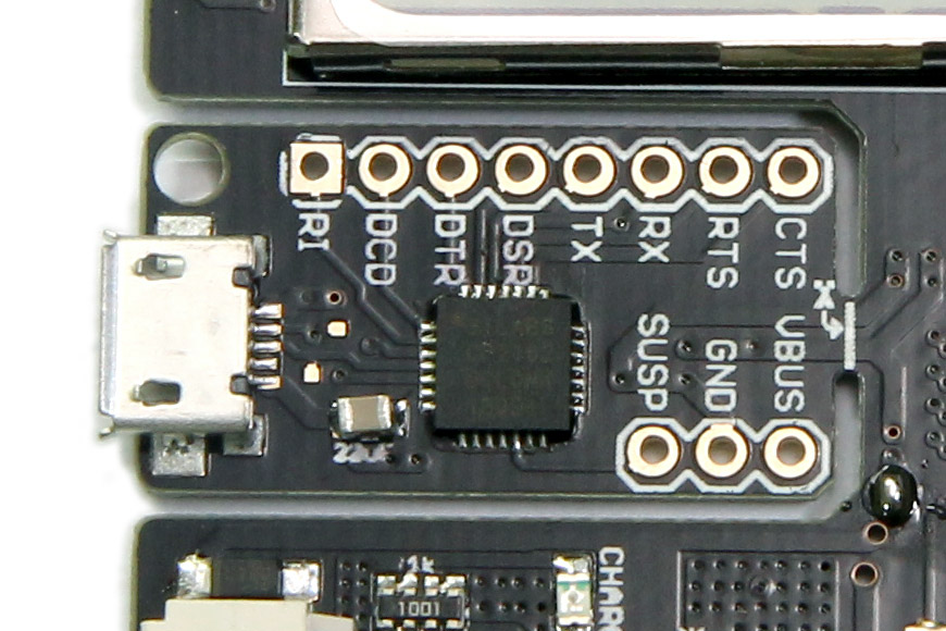
Remember to add test points to everything. We had a few boards where there was USB power to the board but the device was not being detected. Was the USB connector not soldered properly (the data lines was not connected) or was it the CP2102 not working? Add test points for D+ and D- to make it easy to test for continuity, so that those boards can be fixed by hand later. You can see the 2 test points between the USB connector the CP2102 chip below. We also made the QFN pads longer to make it easier to drag-solder in case we need to fix any bridges.
There was also the initial prototype where we didn’t wire up OSC on the LCD. It was really difficult to solder an AWG30 to the PCB traces that mate with the zebra strip. We should have broken it out into test points or pads we can then solder to, which is what we did in later prototypes.
For the initial testing & prototyping, I really wished that we had access to cost-effective, quick turn-around prototyping, like etching or milling the board locally. The Othermill looks to be a promising solution for addressing this.
Firmware
As this was a CTF event, we also wrote some challenges to be uploaded to the badge too. Jacob was the mastermind behind all the challenges.
There was only a single entry point into the challenges. Solving each challenge will advance you to the next. The state is persisted in the SPI flash chip and thus won’t be lost when the battery runs out or when you hit the RESET button.
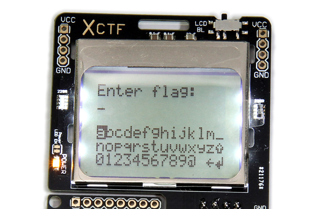
I kinda like the simple framework that I implemented for the badge. There’s a simple applet stack (like the activity stack on Android) where only the top-most applet receives the events, and various UI helpers that display menus with logic for scrolling and an on-screen keyboard that allows users to input the flag for each challenge.
There is also a game embedded as a challenge as well. Originally written for the Arduboy platform, this Dino game was ported by writing a simple wrapper that provides minimal Arduboy functionality. You can see it in action here:
https://twitter.com/_jsoo_/status/744033350814474240Unfortunately, the refresh rate of the LCD is really not very good. Side-scrollers, or any fast animation, are probably not very suitable for this screen.
CTF challenges are never complete without the use of crypto functions. Since the ROM already contains some of these functions, we just need to know how to invoke them. Inspecting the .a files that came with the ESP8266 SDK, it seems that the crypto functions came from hostapd. To use these, we just need to copy the appropriate function prototypes from the header files:
int md5_vector(size_t num_elem, const u8 *addr[], const size_t *len, u8 *mac);

int sha1_vector(size_t num_elem, const u8 *addr[], const size_t *len, u8 *mac);

// aes.h

#define AES_BLOCK_SIZE 16

void * aes_encrypt_init(const u8 *key, size_t len);
void aes_encrypt(void *ctx, const u8 *plain, u8 *crypt);
void aes_encrypt_deinit(void *ctx);

void * aes_decrypt_init(const u8 *key, size_t len);
void aes_decrypt(void *ctx, const u8 *crypt, u8 *plain);
void aes_decrypt_deinit(void *ctx);
You can see all these when we finally open-source the firmware. It is currently withheld to give interested participants more time to solve the challenges. I’ll update this post with the link when it is released.
Mass Upload
To upload the finalized firmware with the challenges into all 100+ badges, I wanted a solution that would detect when you plug in the badge and automatically uploaded the firmware. Then all that’s needed would be a few Raspberry Pis with USB hubs. Connect the badge to a USB port and it should start programming automatically.
StackOverflow recommended the use of pyudev for USB insertion detection which is Python-based (using ctypes instead of compiled native parts, so it’s somewhat more portable). For programming, there’s an esptool written in Python as well 1.
esptool was tested to work reliably at 921,600 baud, which completes programming the device in under 4 seconds.
The Arduino IDE is painfully slow when it comes to development, but since I started with it, it was a bit too late to switch away from it. I enabled verbose uploading, which shows you the path to the Arduino work directory where the compiled sketch is stored (it looks something like %TEMP%/build9db8a...da6e.tmp/sketch.ino.bin). That binary was converted from the compiled ELF and it is what we uploaded to the badge.
I put together a script called massflash.py (for lack of a better name) which we used during the production run. I also made a visualization of the USB events recorded by massflash in a timeline. (In case you didn’t know, I love visualizations.) The length of the bars indicates the time during which the USB device was plugged in.
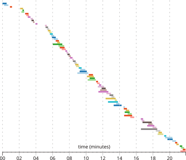
This particular station programmed 88 devices, taking a total time of about 21.9 minutes, which works out to be an average of about 4 devices per minute. While esptool required only about 4 seconds to fully program the device, insertion, removal and checking the device still took some time. There was also some time lost grabbing a new batch of boards to be programmed. From the chart, you can see that the first 3 devices were a sort of test to make sure everything was working. After that we took a whole pile and started chugging.
Tinkering
The main intention was to get the participants interested in hardware hacking. We had to make it easy for them to get started, especially for people who come from a pure software background and are not familiar with hardware.
Fortunately for the ESP8266, there were already several products based around it and many detailed step-by-step guides for users. I highly recommend using the Arduino IDE by following these guides by SparkFun and Adafruit:
- ESP8266 Thing Hookup Guide: Installing the ESP8266 Arduino Addon
- Adafruit Feather HUZZAH ESP8266: Using Arduino IDE
The badge is designed pretty much like both of these devices, except that we added an LCD and buttons to the GPIO pins. You can use the Arduino IDE to upload simple sketches, then move on to work on more complex ones.
We also broke out all the pins to the ESP8266 and the LCD, so you can use this badge as a development board.
Open-Source Hardware
The Eagle CAD files for the badge have been made available on GitHub: https://github.com/jellyjellyrobot/neander. If you are interested in integrating Nokia LCDs directly into your projects, you can use the footprint from here.
The firmware will be made open-source as well at a later date. This will allow interested participants more time to solve the hardware challenges.
Special thanks to Jeremias, Yu Siang, Jacob and the rest of the NUS Greyhats guys who helped to design and assemble all of these badges.
Update 2016-07-19: As promised, the firmware portion has also been open-sourced. You can read about it in my follow-up post here.
- This is not to be confused with esptool-ck, which is a C-based implementation that ships with the Arduino addon. ↩

You mentioned you have the problem about the fabrication turn around time. Have you tried DIY PCB etching?
I have personally done it locally before, can be done within a day and be a useful prototype before you send for actual fabrication.
I have written a blog post about this process using Eagle http://yeokhengmeng.com/2016/03/eagle-file-to-diy-pcb-etching/
The man you should approach is Leon Lim. http://blog.leon-lim.com/2014/07/the-diy-pcb-making-guide.html
Hi Kheng Meng, I did consider etching my own boards but it involves a multi-step process and also deals with chemicals. I have spoken to someone else previously, who advised on where to source for hydrochloric acid locally, but I never did get around to doing it. I just noticed that Leon’s method seems less dangerous than using hydrochloric acid, but there’s still the question of proper disposal. Milling just seems like a cleaner (and safer) solution overall. Nice blog post on the entire process by the way, I might try it someday. So how do you dispose of the chemical waste after etching?
I used hydrogen peroxide and vinegar, safer and does not corrode piping but takes longer to etch. Officially I still have to dispose the waste properly. But unofficially, better not say 😛