I don’t have any dedicated programmers. I have been programming Atmel chips using the USB-to-serial bitbang method.
Recently, I thought I’d get one because doing a re-programming cycle is taking quite a bit of time (a disadvantage of serial port bitbanging).
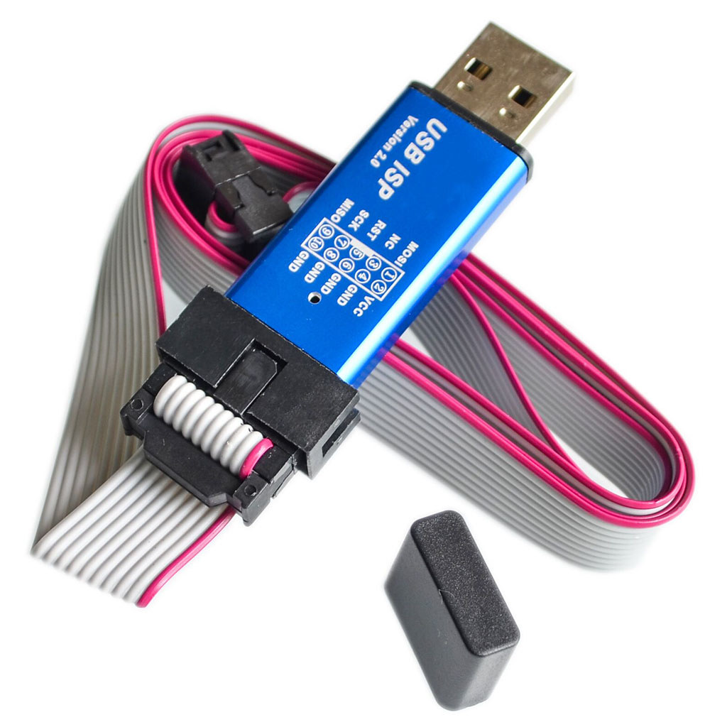
A popular one on Aliexpress seems to be this “USB ISP” one, so I bought one. I chose this one because it has a nice aluminium case, and a pinout diagram imprinted on the case, which is handy. After having so many one-off projects with bare PCBs collecting dust, I now appreciate the importance of having projects in their own box or case.
While it has “USBasp” in the item name, it turns out that this was not a USBasp device, and getting it to work like one takes some effort.
It identifies itself as a zhifengsoft HID device when I plug it into Linux:
usb 3-1: new low-speed USB device number 3 using ohci-platform
usb 3-1: New USB device found, idVendor=03eb, idProduct=c8b4
usb 3-1: New USB device strings: Mfr=1, Product=2, SerialNumber=0
usb 3-1: Product: USBHID
usb 3-1: Manufacturer: zhifengsoft
avrdude does not recognize the device, even after creating an entry with the corresponding vendor/product ID. This particular device was designed to work with their Windows-based UI called ProgISP and will not work with avrdude.
And apparently you can’t just take the USBasp firmware and flash it into this device, because the circuit is somewhat different.
After some research based on the PCB markings, I found these sites that talk about them:
- GreenPhotons: Hacking an AVR programmer
- GreenPhotons: Hacking an AVR programmer II
- USBasp Experiences – efiHacks Wiki
Disassembly
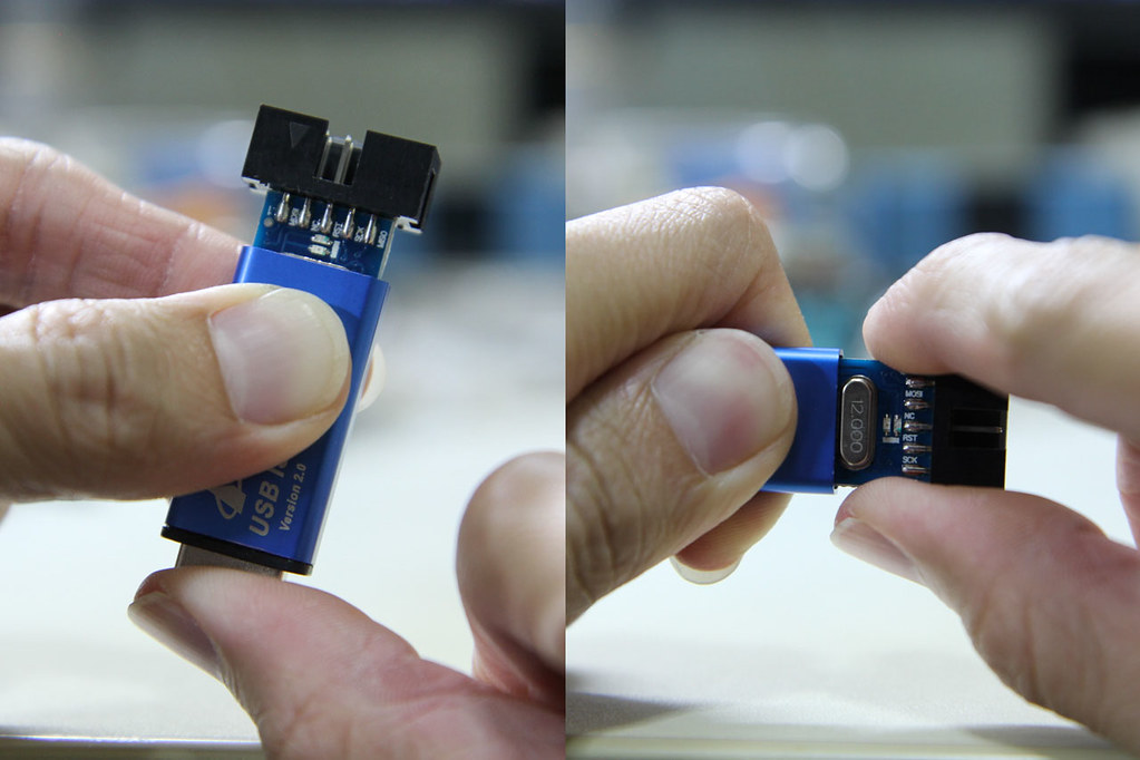
Disassembling the device is simple. While grabbing the side of the case, firmly push the USB connector inwards and the board should slide out the other end. You can then gently pull the board out by the IDC connector.
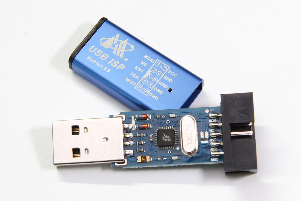
The programmer seems to be based off of the popular USBasp programmer, but modified somewhat (to what end I’m not sure). It lacks some features offered by other USBasp programmers, like the ability to control the target’s clock, or to use 3.3V for certain targets. But at $2 with a nice aluminium case, what more can you ask for?
It’s powered by an ATmega88 (I read that older versions were based on ATmega8). The markings on the board indicate that this is a MX-USBISP-V4.00. You can ignore tHe date because it was never updated; the older V3.02 also has the same date. While the GreenPhotons blog was talking about V3.00, I have verified that this version suffers from the same issue.
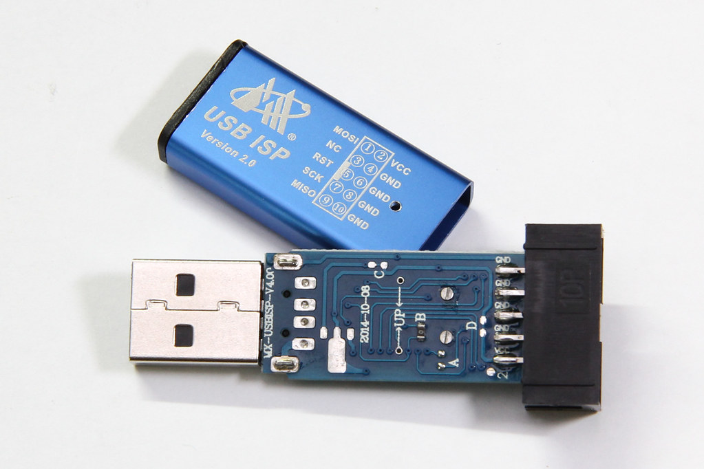
Note that there are provisions on the PCB to add a voltage regulator, and the PCB link marked “C” can be cut to separate USB power from the rest of the system. Link “D” can be cut if you wish to disable target power. However, none of these options were used.
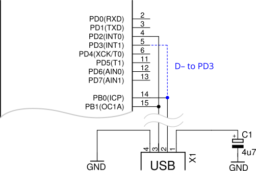
The crucial difference with this clone is that the USB D- pin is additionally connected to PD3, shown here highlighted in blue:
However, in the USBasp’s main() function, PORTD‘s data direction register was initialized like so:
  /* all outputs except PD2 = INT0 */
  DDRD = ~(1 << 2);
This causes the USB D- line to be actively driven from PD3, thereby impeding communication to/from the USB host.
The rest of this post will talk about (1) correcting this problem in USBasp, and (2) uploading the firmware into your zhifengsoft programmer.
Fixing up USBasp
In GreenPhoton’s blog posts above, you will find that he recompiled USBasp with those changes and provided the HEX file.
From what I read in his post, it doesn’t exactly inspire confidence in his provided HEX file:
So I grabbed my 3 ½ year old project and imported it into the 3 versions newer Atmel Studio 7. Compiling showed a couple of errors and warnings caused by the newer configuration settings and the newer, more picky version of GCC, but finally it compiled through now for the ATmega88.
Here instead, I shall just suggest a very simple patch to the HEX file compiled by USBasp’s author himself. Essentially, we just want to modify the DDRD value to make PB2 and PB3 inputs instead of outputs.
Here’s the snippet of the original compiled code that initializes DDRD, via r24:
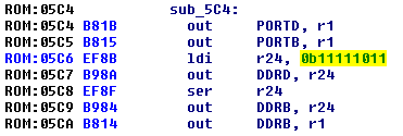
In the ATmega88 HEX file, the corresponding code is located on line 185, and here’s the line with the bytes highlighted:
:100B8000D9F77A9589F708951BB815B88BEF8AB90C
Let’s patch the code to set DDRD = 0b1111_0000, thus the corresponding new bytes should be 0x80EF and the correct checksum for that line should now be 0x17:
:100B8000D9F77A9589F708951BB815B880EF8AB917
With these simple changes made to the HEX file, you can now use this updated file to be flashed into the programmer.
Either that, or you can compile USBasp yourself. I have tried this as well and it wasn’t too difficult — you just need to sprinkle some const keywords in usbdrv.[ch] and it will compile cleanly with avr-gcc.
Re-programming using an Arduino
You can upload a sketch to an Arduino to make it act like a programmer. (I assume you do have an Arduino lying around somewhere?) This programmer is supported by avrdude, so you only need the Arduino IDE to upload the sketch.
The good thing about the Arduino IDE is that it comes with avrdude and avr-gcc as well, so no other additional downloads are necessary. I unzipped the Arduino IDE zip file into C:\. You can find the avr binaries under hardware\tools\avr\bin, and the avrdude.conf resides in hardware\tools\avr\etc. You can either go to the bin directory to run avrdude, or you can add the bin directory to your %PATH%. The same can be applied to the Linux and Mac versions (I think).
The USBasp programmer was designed to be programmed via the same port it uses to program the target. All the ICSP pins are connected through, except for RESET, which is used to control entry into programming mode. That pin can be connected to RESET via a jumper when programming is required.
We will choose to use the “old wiring style” in the Arduino sketch. This can be done by looking for the following lines in the sketch, then uncommenting the #define:
// Uncomment following line to use the old Uno style wiring
// (using pin 11, 12 and 13 instead of the SPI header) on Leonardo, Due...

#define USE_OLD_STYLE_WIRING  // <-- uncomment this
Use the Arduino IDE to upload the modified sketch into your Arduino. After you are done, close your Arduino IDE, in case it also tries to open the serial port.
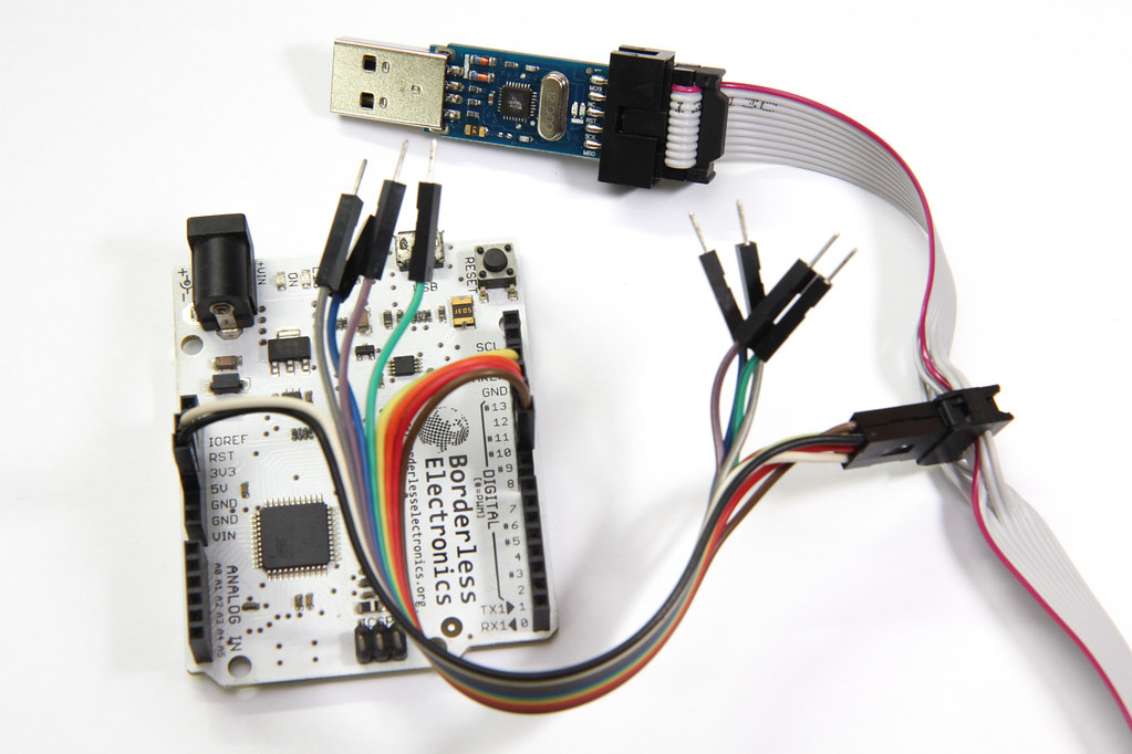
You should then wire up your Arduino to the programmer’s ICSP connector by following the code in the sketch. This is where the pinout diagram imprinted on the case comes in handy.
#define RESET       10
#define PIN_MOSI    11
#define PIN_MISO    12
#define PIN_SCK     13
Also, remember to hook up Vcc and GND, so you should have a total of 6 pins connected. Here, I have spliced a 6-pin IDC connector into the provided programming ribbon cable. You can more easily connect to “standard” 6-pin ICSP headers that way.
For the final step, you will need access to the programmer’s PCB to enable self-programming.
Insert a wire to bridge the --> UP <-- holes as indicated on the rear of the programmer board. That will bridge the RESET on the programming header with the RESET on the ATmega88 to allow it to be programmed. The PCB holes are so small that I had to use AWG 30 wire-wrapping wire.
Now, verify that your Arduino programmer is working by running the following avrdude command from the bin directory. Use -P to specify your serial port, which in my case is COM15.
If you are using an Arduino Leonardo as your programmer, you should specify -c arduino, but if you are using an Arduino Uno, you will instead need to specify -c stk500v1 -b 19200.
C:\arduino-1.8.3\hardware\tools\avr\bin>avrdude -C ..\etc\avrdude.conf -vv -c arduino -P COM15 -p atmega328

avrdude: Version 6.3, compiled on Jan 17 2017 at 12:00:53
  .
  .
  .

avrdude: AVR device initialized and ready to accept instructions

Reading | ################################################## | 100% 0.01s

avrdude: Device signature = 0x1e930a (probably m88)
avrdude: Expected signature for ATmega328 is 1E 95 14
         Double check chip, or use -F to override this check.

avrdude done.  Thank you.
If avrdude can successfully read the device signature and identify the target device properly, it means that the programmer is working. Here, despite me specifying the part as an ATmega328, it still correctly detected the device as an ATmega88 (m88).
If you get a 0xffffff or 0x000000 device signature instead, your programmer might not be working correctly. Check your wiring to ensure you have the connections right.
Now using avrdude, your Arduino should be able to read the device signature and fuses. The zhifengsoft programmer already has the correct fuses programmed in, so nothing needs to be changed. Refer to the USBasp README to find out what are the lfuse and hfuse values to use for different processors.
All that’s left to do is to program the updated HEX file with avrdude:
avrdude -vv -c arduino -P COM15 -p m88 -U flash:w:usbasp.atmega88.2011-05-28.hex:i
Again, if you are using an Arduino Uno as your programmer, you will need to modify your command slightly:
avrdude -vv -c stk500v1 -b 19200 -P COM15 -p m88 -U flash:w:usbasp.atmega88.2011-05-28.hex:i
where usbasp.atmega88.2011-05-28.hex is the path to the HEX file you have just patched above, and i stands for Intel HEX format.
Verifying
After programming is complete, your programmer should now have the blue LED lit to indcate it is powered on. When there’s activity, the red LED will flash.
Plug in the programmer into a USB port and verify that it can be detected by the OS. If the OS does not detect your programmer, it could be that you flashed the wrong HEX file without the updated DDRD value.
Congratulations, you are now the proud owner of a USBasp programmer.

thanks very much for this post, Ihave my usbasp working now
Thank you for making this post, as I am now a proud owner of a usbasp. Got stumbled a little bit at the reprogram part, avrdude recognize m328p not m88p. But you can just add more parameters to avrdude to make it recognize the chip.
This works for me (already in folder containing hex file): avrdude -c stk500v1 -p m88 -P /dev/ttyACM2 -b 19200 -U flash:w:usbasp.atmega88.2011-05-28.hex:i
Dude ! Thank you for the comprehensive write-up to hack this chinese clone. and for the thing on using Arduino IDE to ISP program the chinese clone ! Right now i am messing with making a USB-ASP from its circuit diagram using a blank ATmega8A on a breadboard and saw your post. but am i missing something ? I mean why not cut the track that goes to PIN 14 to PIN 5 on the ASP clone so it dosen’t interefere with D- communication data from the PC ? That should avoid all the code recompilation and loading , right ? Raj (India)
Hi Raj, yes, you can cut the PCB track but some people (like me) prefer a software-only fix. That way, it would still be possible if you ever need to undo the “fix”.
Thank you very much, this tutorial is very usefull and is working.
Many thanks for this very useful information. Your way is the best solution, I tried it and it worked from the first try.
This is very Informative and useful post,thanks for your solution.but i have stumbled on “Re-programming using an Arduino” part.I have hooked up programmer with arduino as you described, but avrdude seems to detect on board atmega328p instead of programmer atmega88. any idea what might have gone wrong for me? 😦
That sounds like avrdude is actually trying to program the Arduino board instead of the USBasp programmer.
You can check by disconnecting the ICSP connection to the programmer and avrdude should complain because it now can’t find the chip. If it still reports something when the Arduino is not connected to anything, it means avrdude is talking to the ATmega328 on the Arduino itself.
Yeah, you are right, arduino still detect atmega328p after disconnecting the USBasp. also tried with an atmega16 just to upload a simple blink hex file,same issue as before.
Me too. please tell me how to solve this problem. i will very grateful.
I have tested with an Arduino Uno and realised that the avrdude command needs to modified slightly. I’ve updated the blog post accordingly, and it should work properly now. Let me know if you are still having problems.
I finally flash it correctly. thank you for you tutorial
Thank you very much for the usefull tutorial. I got my mx-usbisp v4.0 working BUT only after removing the jumper wire from PCB. Perhaps you could add a reminder regarding this at the begining of the “Verifying” chapter, some of us are beginners…
I want to transform a clone fischl in zhifengsoft prog. Because to me work fine this. After i wrote fischl with zhifeng firmware said “unrecognized device” What’s the hardware difference between that two programmers?
See the diagram above. You likely need to connect
PD3toD-on the USB. I’m assuming the Zhifeng programmer drivesPD3instead ofPB0.I used an ohmmetter ant tested: on both pcb PD2 (pin 32) is connected to D- (pin 12).
The
D-pin I was referring to is to the USB connector, not on the ATmega. Refer to the schematic diagram in the post above, the missing connection I’m talking about is the dotted line in blue. If you need to compare, the fischl schematic is available at https://www.fischl.de/usbasp/. You will see that the connection is not present.Yes, i understud. But on both PCB (Fischl and Zhifeng) only ONE of pins USB is linked at 2 pins of Atmega. The link you purpose is not present neither on Fischl or Zhifeng. If can and is usefull, see the link with firmware Zhifeng read from programmer.
That can’t be true. The whole purpose of this post was to make the Zhifeng clone work with the original Fischl firmware, and the main reason why it doesn’t work is because there is an additional link on the Zhifeng clone, the one that was highlighted in blue. That additional connection prevents the Fischl firmware from working. If the link is not there, then you won’t need to do anything at all — just flash the Fischl firmware and everything would work. Nobody would need to refer to this guide, and nobody else would have needed to write any guides.
OK, understud..
I will try to extract schematic from both PCB and compare.
Thank you for help.
A little difference exist: After i reflash Fischl with Zhifeng, the RED LED is ON instead GREEN LED. The rest of differences will see.
Hi Folks,
I found this very useful article for few days ago. I bought two cheap “AVRISP” dongles some days before, but I could not use them as “usbasp” with avrdude under Linux – as you discussed the main problem. Today I had a little time to try reflashing one of the two dongles with a modified original hex file, as it is subscribed above but it was unsuccessful – flashing finished correctly, but USB device became unrecognizable. When I reflash the original content it is working as before – hardware is not damaged. So I had done some investigations around the dongle with an ohmmeter. The followings came out:
– my device is “MX-USBISP-V5.00”, dated 2015-03-18 (not a good print, maybe date is 2018-03-18)
– I could read out the contents of the microcontroller on the board
– circuit is based on ATmega88V (TQFP package)
– series resistors on lines D+ and D- are 100 ohms (R1 and R2 on original USBASP schematic)
– USB D- pullup resistor is 1.8 kohm (R3 on original schematic)
– USB D+ is connected to PB1 and PD2 pins (through a serial resistor)
– USB D- is connected to PD3 and PD5 pins (through a serial resistor)
– ICSP RST pin is connected to PB2
– ICSP SCK, MISO, MOSI are connected to PB5, PB4, PB3, respectively
– PC1 drives a red LED
– PC0 drives a blue LED
As you can see from the above, wiring of USB D- is totally different than the original. I think, I should do a “clean” compile from the original source with modified pin bindings – I will try it soon.
Zoltan
That’s interesting, thanks for sharing! I’m assuming this is the same problem as what Liviu was facing as well — basically the USB pins are connected to different pins that what we expected. Changing the code to reflect these new pins in the fischl firmware should work.
Well… Yesterday night I had time to analyze the problem with my dongle. Further investigations were made about pin mappings. First of all I noticed, that pinout of Atmega88 was suspicious in the document that I found first (http://ww1.microchip.com/downloads/en/DeviceDoc/Atmel-7530-Automotive-Microcontrollers-ATmega48-ATmega88-ATmega168_Datasheet.pdf): pin9 and pin12 are both marked as PD5. Double checking it from documents available on Microchip’s ATmega88 product site pointed to the mistake: pin12 is PB0 indeed, so my circuit pinout is the same as it was described in the article above! That’s why the modified hex firmware should have been worked.
After clarifying pinout I downloaded the original USBASP firmware source and made a fresh compiled version of it for ATmega88, but it did not work too. Today morning I modified the USBASP firmware source files to do an endless pin-testing loop on the LEDs and USB data lines. Unfortunately, during flashing the dongle, mega88 started not responding at a point. After it I could not talk to this mega88 at all. Maybe this was really not a 100% part before, it could have caused the weird behavior.
I took the 2nd dongle (I never buy only 1 pc of any part from China…) and uploaded my pintesting firmware on it. It was running well, all of our pins were waggling as expected. After pintesting I had uploaded the freshly compiled USBASP firmware – of course, port initialization was modified according to extra D port pins connected to USB data lines. The firmware runs well on 2nd dongle, it is stable and fully functional.
Conclusion:
The ver5.00 hardware not differs from earlier ones (sorry for mistaken alert), it can run modified mega88 hex firmware as it is discussed in the article. One of my two dongles likely was not a 100% condition one, causing the unexpected behavior.
Zoltan
On both v5 PCBs I got there is a zero-ohm resistor forming the bridge between PB0 and PD3. Just remove the resistor and flash the USBasp firmware.
[…] https://irq5.io/2017/07/25/making-usbasp-chinese-clones-usable/ […]
It works, thanks for this nice share.
hi thanks for this step by step
is there a downloadlink for the correct hex file?
grtz from holland
Hi edensan, I did not provide a modified hex file because it is quite simple to do it yourself. The original hex files are at the USBasp site here. Download the compiled hex file from there and use Notepad to make the one-line change accordingly. If you don’t want to do this yourself, you can also download a different compiled version from the GreenPhotons blog, which should also work the same. Hope that helps.
I used the modified Atmega88v firmware from the tutorial: “GreenPhotons: Hacking an AVR programmer II” worked perfectly on my chinese USBasp clone (MX-USBASP V5). Thanks for sharing!
[…] Szerencsére az ISP lábakon keresztül ő is programozható, és az Interneten találtunk egy bloggert, aki belefutott ugyanebbe a problémába. Aki szeretné a teljes sztorit elolvasni, és tud külföldiül, annak ajánlom, hogy az eredeti […]
If anyone using arduino nano as a ISP programmer, remember that you need to put an electrolytic capacitor on the Arduino nano RST and GND pin. I’ve used 4.7uF and works!
when installing usbasp driver select libusb-win32(v.1.2.6.0) instead of the default driver. This solved my problem after uploading the above mentioned hex file.
I had a new PCB version MX-USBISP-V5.00 and I can confirm this solution (and the hex file from GreenPhoton’s blog -> 20161227_mega88_usbasp.hex) works with the new version 5.
Thanks 🙂
Also here is a direct link https://www.sciencetronics.com/greenphotons/?p=1937 (no need to change fuses on version 5)
[…] -cusbtiny for a USBtiny). If you don’t have another ISP programmer, you can use an Arduino. This guy shows you how, as well as another way to get […]