Seeedstudio Fusion PCB Review

Fusion PCB is a PCB service from Seeedstudio. They have been offering PCB prototyping service since I made my first board in 2011. It has recently been revamped a little, tweaking prices and options, as well as integrating an online Gerber viewer from EasyEDA. I was invited to give Seeedstudio’s revamped Fusion PCB service a try, and since I had some boards in the pipeline for manufacture, I thought why not?

You can configure various options for the PCB, such as board thickness, copper pour and surface finish. You can also make flex PCBs or aluminium for better heat sinking, as opposed to regular FR4. These options will of course come at a price. However, you can select various colours for your PCB at no additional cost.

The Boards

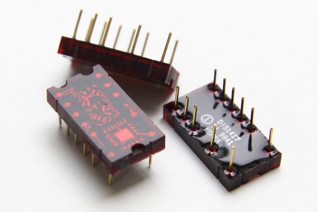
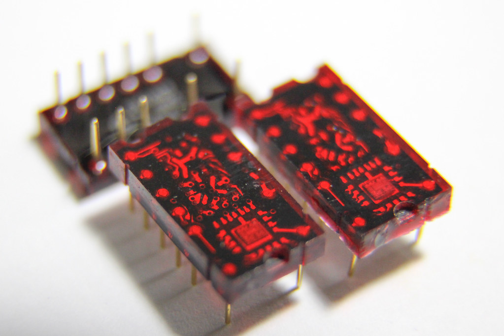
I ordered 2 sets of boards in total. I’ve decided to opt for an ENIG finish for the TIL311 display boards, just because it looks nicer in gold. The boards are manufactured with black solder mask, making the gold pads stand out better.

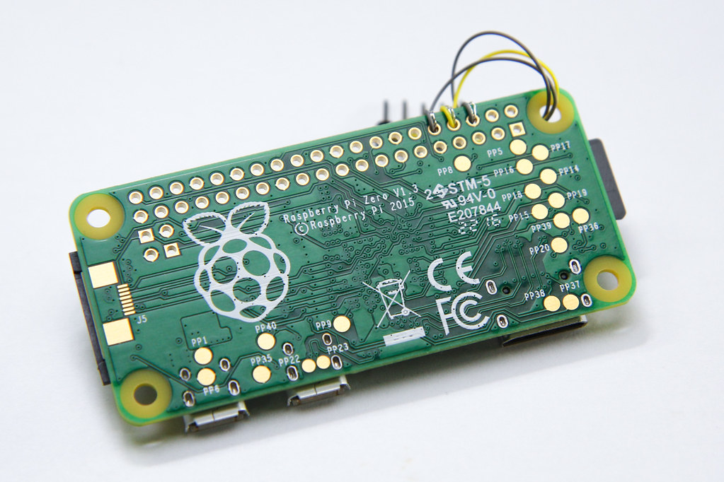
I’ll describe the display board in a separate post after I’ve assembled it. For now, here’s what 4 of the boards look like, component side up:

TIL311 display PCBs

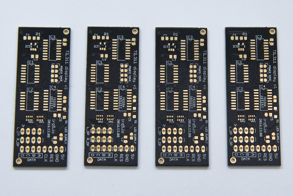
Like most PCB prototyping services, they track your order by printing some kind of order identifier onto each PCB. Usually they try to put this identifier underneath a component like an IC so it gets hidden when the board is fully populated, but sometimes they put it somewhere prominent, like under your product name. On this board, the identifier sits under IC4 but for the other board, it was under the product name.

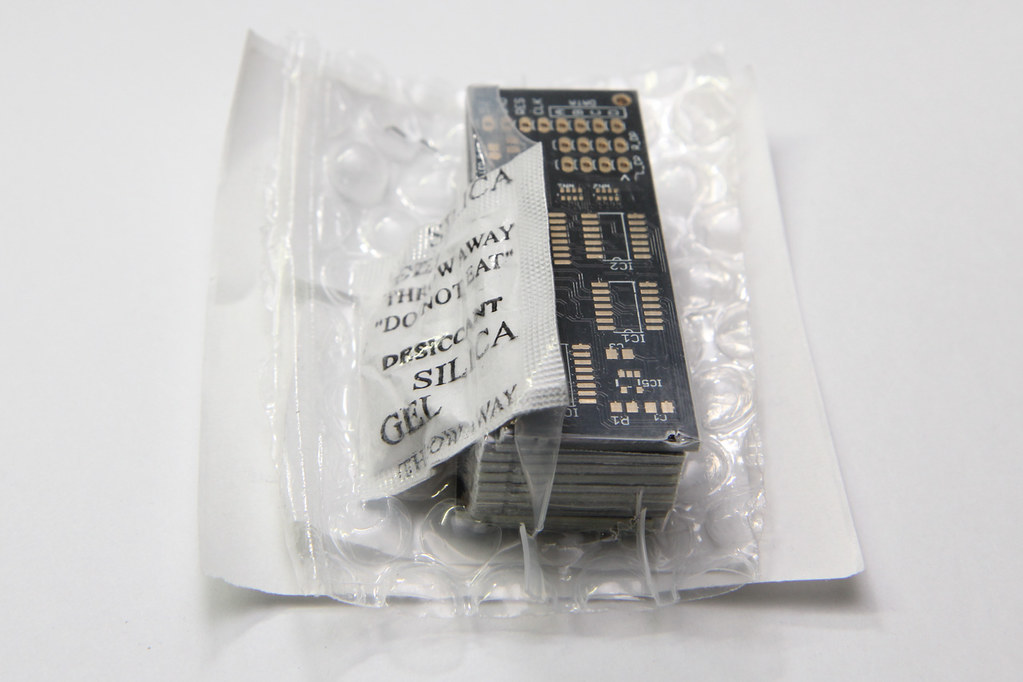
The PCBs arrived in a shrink-wrapped bubbly packaging to protect the boards. There was also a desiccant thrown in for one set of the boards to keep it dry.

PCBs arrived in bubbly shrink-wrap

Continue reading

Raspberry Pi Zero as Multiple USB Gadgets

In case you haven’t heard, the Raspberry Pi Zero is the smallest, most low-cost device in the Raspberry Pi family, but it’s also the hardest to find. It has two Micro-B USB ports, one for power and another functions as a dual-role USB OTG port.

Raspberry Pi Zero, back side

One of the more interesting uses for the Raspberry Pi Zero is to get it to behave as a USB device, just like your USB flash drive, for example.

There have been several guides written already, such as the Adafruit one, but most of them were based on the old kernel gadget drivers, like g_serial and g_ether. It still works, but not as flexible and likely to be deprecated in future.

Continue reading

Retro LED Displays

When I saw this post on Hackaday, I thought the display looks cool. Even the people who commented on the post thought so too. This board that you see in the post monitors the bus for the Z80 in the RC2014 retro Z80 computer kit.

After some searching and the wisdom of the Hackaday crowd, I bought a few of them from eBay. It turns out that these displays are no longer being manufactured anymore. These used to be made by Texas Instruments, the TIL311 or DIS1417.

TIL311 / DIS1417 Displays

I like how the display looks like a pseudo LED matrix, forming a 7-segment display. They could have made the edges totally flat, just like a 7-segment display, but they chose to round the corners of certain digits and letters, like 0, 2, 8, A and others.

TIL311 font map

Each display has a built-in chip at the bottom of the digit, which you can see under bright lighting in close-up photos. The chip handles the latching and display logic, and contains a constant-current driver for all the LEDs to output a single hex digit (0-9, A-F). This was handy for old-school logic systems (like the Z80) because each display handles 4 bits, exactly a single hexadecimal digit. You could also interface this display easily without a microcontroller, as opposed to a display that that speaks I2C.

From the date code in the photos, you can that these displays were made in Korea in 1998. The pins look like they are made of gold, or gold-plated.

Continue reading

X-CTF 2016 Badge Firmware

As promised, we are releasing the source code for the X-CTF badge, about 1 month after the event to give interested participants the chance to take a crack at it. If you are interested in the badge design process, check out my previous post on the hardware aspects.

Jeremias and Jeremy gave a talk at one of the Null Security meetups. Check out the slides if you haven’t already. In one part, Jeremy talks about the custom firmware he wrote for his badge and the additional challenges he set up for partipants to get more points. The 2nd part of the talk covers the electronic badge and challenges.

The Challenges

The challenges try to exploit the nature of being a self-contained electronic device. Rather than trying to replicate more CTF puzzles and simply placing them into the badge, we specially designed them for the badge.

You can find the answers to the badge puzzles (and the main CTF puzzles) in the X-CTF GitHub repo, which was released shortly after the event.

Since there’s only a single entry point into the set of challenges (meaning you must solve each puzzle before getting to the next), the puzzles must be designed with increasing levels of difficulty; too difficult and the participants will totally give up.

Stage 1: Catch Me If You Can

animation of challenge 1

I particularly like this one. Unlike a program running on the computer, you can’t easily snapshot the state of the program, nor try to influence (slow down) its execution.

Continue reading

Designing the X-CTF 2016 Badge

X-CTF 2016 badge with Lithium-ion battery attached

I had the opportunity to collaborate with some NUS students to design the electronic badge for their X-CTF event this year.

The purpose of the badge was to inspire more people to take an interest in hardware hacking, or to get them started on electronics. With so much hype on the Internet-of-Things (IoT) these days, what better idea than to let participants take home their very own IoT device. The super low cost WiFi chip, Expressif’s ESP8266, made this possible. We also wanted it to be shaped like a gaming device, with a D-pad and an LCD.

You can see the final badge design above: a ESP8266-based board with a backlit monochrome Nokia LCD, D-pad and a SELECT button. Powered by a lithium-ion battery, charged via the USB port, which also provides a serial connection to the ESP8266.

I was inspired by the SyScan 2015 badge. It was so simple and spartan: a monochrome LCD, an LED, a 5-way joystick switch and a 32-bit ARM processor (on the back). As the regulator was built-in and it runs all the way down to 2.4V, there was no need for an external regulator.

SyScan 2015 electronic badge

Continue reading