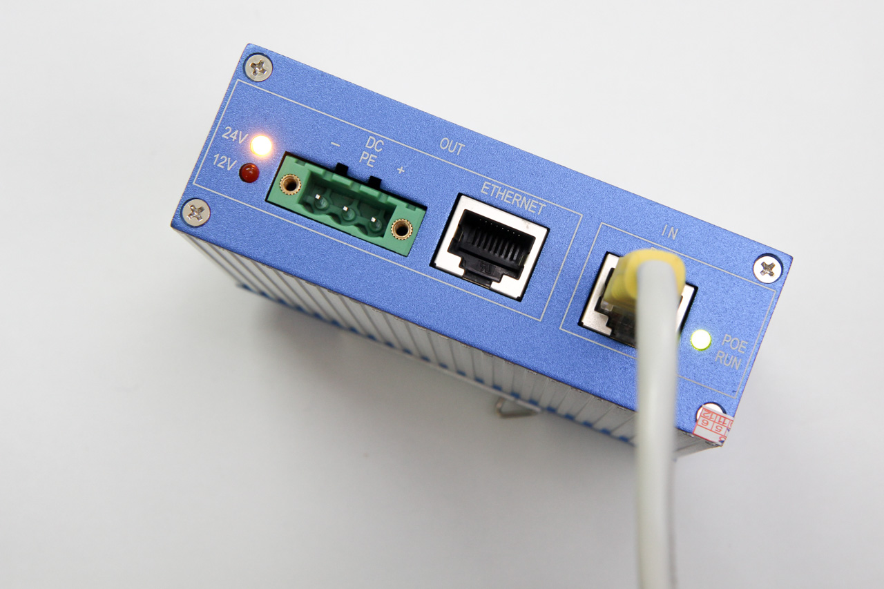
I have been looking around for Power over Ethernet (PoE) devices to supply power to some networking hardware that will be located in a remote location, without a convenient power outlet. These networking hardware do not have built-in PoE support, so I have to find both an injector and a splitter device.
PoE is typically found on enterprise networking equipment, which usually means a higher price tag. Not wanting to spend a ton on PoE hardware, I did some research to understand what was required to make it work.
Hopefully this will help you understand PoE, how it works, and what to look out for when shopping for PoE hardware that are suitable for your needs.
PoE Quick Guide
Active vs Passive
Passive adapters are very simple, and you will see them mostly as an RJ45 socket with pigtails for power and Ethernet. These adapters do not contain or require any circuitry, which also explains why they are the more inexpensive option between the two.
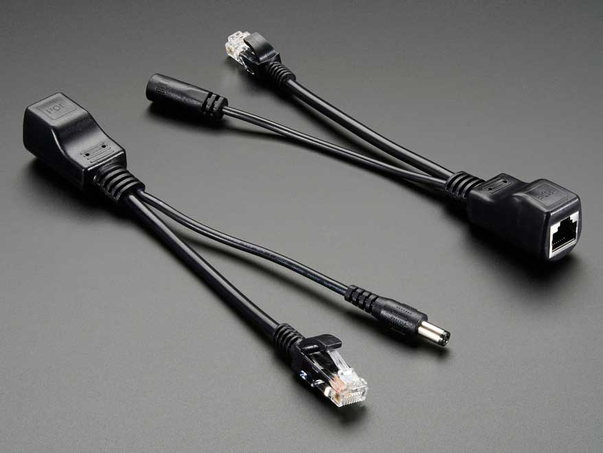
Active PoE (the real Power over Ethernet) on the other hand requires some negotiation between the two devices, called the PSE (power sourcing equipment) and the PD (powered device).
There are several PoE standards. 802.3af, 802.3at and the newer 802.3bt. The difference is mainly in the maximum power is made available to PDs:
- 802.3af – 15.4W
- 802.3at – 30W
- 802.3bt – 60W to 100W
802.3bt was just ratified in the last year (2017). In the time span before the 802.3bt standards was ratified (~8 years!), some companies like Linear Technolgy & Cisco Systems took it upon themselves to find other means of carrying up to 60W. The result was LTPoE++ and UPOE, an evolution of the existing 802.3af/at standards, but may not be compatible with the final standard arrived at by committee.
Mode A or B
The Cat5 cable has 8 wires, forming 4 twisted pairs. For 10/100Mbps, only 2 pairs are used: pair 1/2 for Tx and pair 3/6 for Rx.
The modes refer to how power is delivered to the device:
- Mode A: pairs 1/2, 3/6
- Mode B: pairs 4/5, 7/8
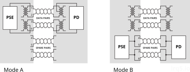
Mode A uses the data pairs for power. This mode is well suited for very old cabling which didn’t connect all 4 pairs end-to-end. You might see some manufacturers calling this mode End-span wiring. To carry power over the same data cables, phantom power delivery is used (more on this later).
Mode B uses the unused (or spare) pairs for power. You might see this being referred to as Mid-span. This type of wiring is easier because it knows the pair is not carrying any data and thus can be wired directly.
Unlike mode A, mode B in this form cannot be used to carry power for Gigabit networks, because a Gigabit connection will require all 4 pairs for data transmission. Power must therefore be delivered via centre-tapped transformers, or what is known as phantom power. How this works is explained in a 1944 US Army video on telephone electronics.
Power Capacity
The committee decided that two pairs of Cat5 wire should only carry up to 30W of power; which two pairs will depend on whether mode A or B wiring is used.
For higher power capacity like 802.3bt (PoE++) or the non-standards-based UPOE and LTPoE++, the other 2 pairs will be paralleled up, making use of all 4 pairs to carry higher currents.
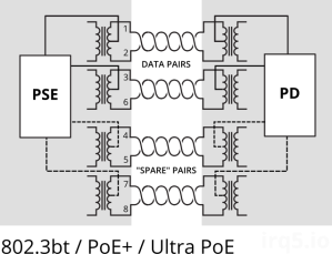
For Gigabit Ethernet (1000Mbps), because all 4 pairs are used to carry data, power (regardless of which pairs used) must be delivered via phantom power delivery.
Why use Active PoE?
In short, because it is safer.
It was designed with the consideration that not all network equipment can accept power, whether via the data pairs or spare pairs.
During the detection phase, the PSE will apply 2.7V to 10V to check for a known resistance. This voltage is low enogh and also for a brief period such that it wouldn’t matter if the device on the other end is shorted. A device that was not designed for PoE would thus never see any higher voltage beyond the detection phase.
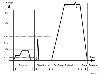
In contrast, passive PoE makes the full voltage and current available on the data/spare pairs. If the remote end is using a magnetics configuration that shorts out the centre taps, the 30W of power would just melt the port (one would assume).
Integrated PSE controller chipsets will also contain features like overcurrent protection, thermal cut-offs and surge protection, etc. which all contribute towards keeping your PDs safe from harm.
Finding Low-Cost PoE Hardware
It was quite a daunting task, trawling AliExpress for PoE injectors & splitters. The description or specifications for items are also not accurate; it’s like finding a USB cable listed as capable of carrying 2A when in fact it does not.
While passive injectors are the cheapest option, most of them are not meant for Gigabit Ethernet. Recall that Mode B wiring is the easiest and most low-cost method for building a passive device, and that is what you will mostly find. This wiring configuration does not pass through all 4 pairs and thus cannot be used for Gigabit.
Most active PoE splitters output 12V, or 5V via USB. This is largely due to the fact that these devices were meant for IP cameras, which operate at that voltage. If your target device uses a non-standard voltage, you will have difficulty finding a suitable (and yet low-cost) splitter.
Here’s a list of hardware I’ve found; which one is suitable for you depends on your requirements:
- Do you need 1000Mbps, or just 10/100Mbps would suffice?
- What voltage does your target device require?
- How much power does it require? 13W, 30W?
Continue reading →

