I was prototyping a circuit on a piece of veroboard using SMD components and I needed a 2V supply from my FTDI cable. Of course I didn’t have any SMD regulators handy, so I thought I would use the simplest regulator – a zener diode. But it’s not like I have a 2V zener diode lying around either, so I thought maybe I could use an LED instead, since its forward voltage is close to 2V (for the red/green ones).
A zener regulator is set up like this:
 The concept is simple: zener diodes are specially designed to have a specific breakdown voltage (in my case 2V) when put in reverse. The result is a 2V voltage drop across the diode, and hence, Vout. Since I didn’t have a zener diode, I thought I would use a regular LED in its place, but placed in forward bias (so that it lights up).
When I tested the circuit however, I realised the voltage drop across the LED was less than 2V. I missed an important point: the current-voltage curve.
 Observe the LED current-voltage curve on the left and the zener diode current-voltage curve on the right. You will notice that the zener diode has a steeper curve compared to the LED. Apparently to avoid blinding myself, I had limited the LED current to about 10mA. I missed the fact that at 10mA the voltage drop across the LED is now only ~1.8V. To get 2V across the LED, you need at least 20mA, which would be too bright as an always-on indicator.
This also answers a question I previously had of whether I can use an LED in place of a zener diode for crude voltage regulation. One of the techniques used by VUSB devices to limit the D+ and D- voltage is to use a pair of 3.6V zener diodes (solution B). The SparkFun AVR Stick uses blue LEDs so that they also double as activity indicators, but from the user comments, it is clear that this causes problems.
If you want to use an LED for voltage regulation, remember to check the current-voltage curve.
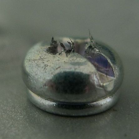
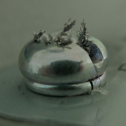 Here’s a view from the top. If not for the fact that this screw has a groove into which you can insert a flathead screwdriver, you probably won’t be able to remove this at all.
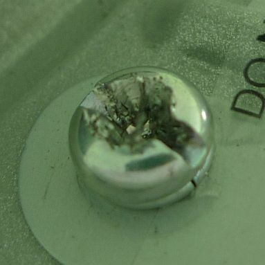 I actually needed to unscrew the bottom cover (which they term the canopy) to check if there’s a serial number printed on the motor hub. I’ve tried 3 different Phillips screwdriver and none of them can grip the screw properly.