Some time last year, Mats Engstrom shared his PHP script for generating commands to move components in CadSoft Eagle to form a perfect circle. If you look at the screenshot, it’s mainly made up of MOVE and ROTATE commands – relatively easy.
Eagle has what it calls user language programs (ULPs) for doing some simple scripting with the ability to display a dialog for user input. I decided to try my hand at creating a ULP that creates these circular layouts. The main advantage of using a ULP is that it has access to your board layout, saving you from some typing. You can also easily iterate through different parameters quickly and without hassle.
I shall illustrate briefly how this circular layout ULP can be used for doing various kinds of layout, with help from some open-source projects with Eagle CAD files.
Ringo3 Clock
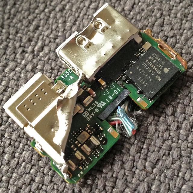
The most common use for a circular layout is in clocks. Conveniently, Mats has a project called Ringo3. For photos of the PCB and assembled clock, see this Dangerous Prototypes forum topic.
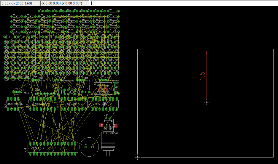
Delete the existing board (.brd) file to start with an empty PCB created from the schematic. We shall take (2.00, 1.60) to be the centre of the circle, as shown. Eagle 6 introduced a dimensioning tool, used here to show the radius of the circle (1.5″) – handy but not a must.
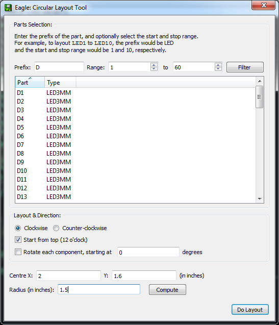
The circular layout ULP has 3 main sections: (i) parts selection, (ii) layout options, and (iii) circle centre point & radius. For parts, enter D for prefix and 1 to 60 and click the Filter button to select components D1 – D60 for layout. The handy table shows you the currently selected list of components. Enter 2 and 1.6 for the circle centre X, Y values that have been identified. The radius has been marked by the dimensioning tool as 1.5. The layout direction is “Clockwise” and we want to place D1 at the top “12 o’clock” position. Click the Do Layout button, and OK to start the layout.
You should see the components move into place as shown in the next figure.
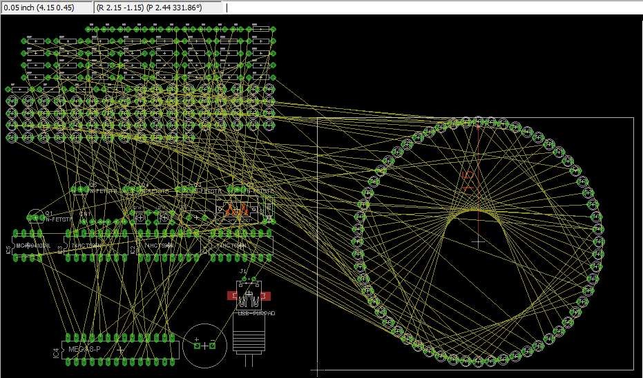
If you make a mistake, you can always just hit Undo or hold down Ctrl+Z until all the components were back at their original positions.