I don’t have any dedicated programmers. I have been programming Atmel chips using the USB-to-serial bitbang method.
Recently, I thought I’d get one because doing a re-programming cycle is taking quite a bit of time (a disadvantage of serial port bitbanging).
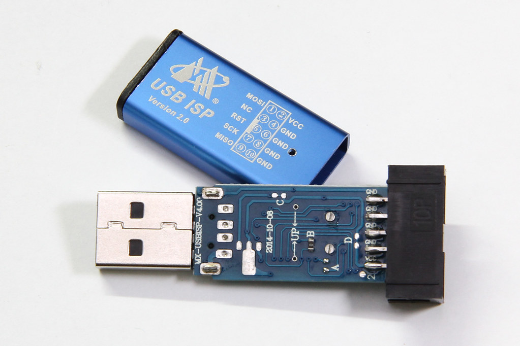
A popular one on Aliexpress seems to be this “USB ISP” one, so I bought one. I chose this one because it has a nice aluminium case, and a pinout diagram imprinted on the case, which is handy. After having so many one-off projects with bare PCBs collecting dust, I now appreciate the importance of having projects in their own box or case.
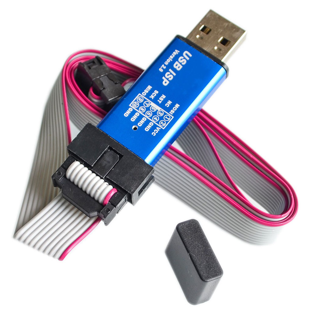
While it has “USBasp” in the item name, it turns out that this was not a USBasp device, and getting it to work like one takes some effort.
It identifies itself as a zhifengsoft HID device when I plug it into Linux:
usb 3-1: new low-speed USB device number 3 using ohci-platform
usb 3-1: New USB device found, idVendor=03eb, idProduct=c8b4
usb 3-1: New USB device strings: Mfr=1, Product=2, SerialNumber=0
usb 3-1: Product: USBHID
usb 3-1: Manufacturer: zhifengsoft
avrdude does not recognize the device, even after creating an entry with the corresponding vendor/product ID. This particular device was designed to work with their Windows-based UI called ProgISP and will not work with avrdude.
And apparently you can’t just take the USBasp firmware and flash it into this device, because the circuit is somewhat different.
After some research based on the PCB markings, I found these sites that talk about them:
- GreenPhotons: Hacking an AVR programmer
- GreenPhotons: Hacking an AVR programmer II
- USBasp Experiences – efiHacks Wiki
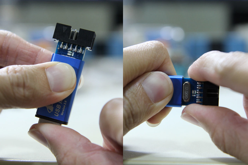
Disassembly
Disassembling the device is simple. While grabbing the side of the case, firmly push the USB connector inwards and the board should slide out the other end. You can then gently pull the board out by the IDC connector.
The programmer seems to be based off of the popular USBasp programmer, but modified somewhat (to what end I’m not sure). It lacks some features offered by other USBasp programmers, like the ability to control the target’s clock, or to use 3.3V for certain targets. But at $2 with a nice aluminium case, what more can you ask for?
It’s powered by an ATmega88 (I read that older versions were based on ATmega8). The markings on the board indicate that this is a MX-USBISP-V4.00. You can ignore tHe date because it was never updated; the older V3.02 also has the same date. While the GreenPhotons blog was talking about V3.00, I have verified that this version suffers from the same issue.
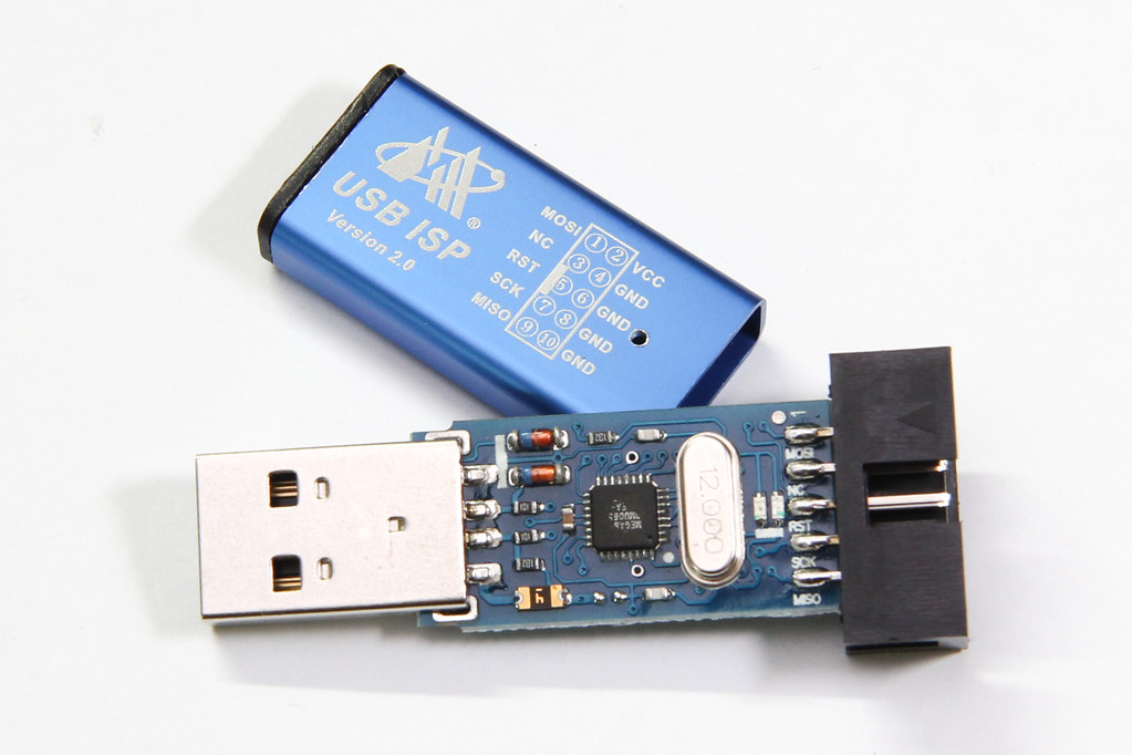
Note that there are provisions on the PCB to add a voltage regulator, and the PCB link marked “C” can be cut to separate USB power from the rest of the system. Link “D” can be cut if you wish to disable target power. However, none of these options were used.
The crucial difference with this clone is that the USB D- pin is additionally connected to PD3, shown here highlighted in blue:
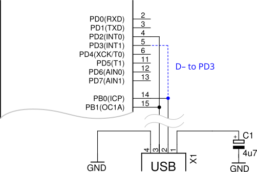
However, in the USBasp’s main() function, PORTD‘s data direction register was initialized like so:
  /* all outputs except PD2 = INT0 */
  DDRD = ~(1 << 2);
This causes the USB D- line to be actively driven from PD3, thereby impeding communication to/from the USB host.
The rest of this post will talk about (1) correcting this problem in USBasp, and (2) uploading the firmware into your zhifengsoft programmer.