ONV PD3401G PoE Splitter Teardown & Review

Continuing my PoE series, I bought the ONV PD3401G, an active PoE splitter that is capable of extracting up to 60W (24V @ 2.5A) from the PSE. It is housed in a small aluminum extruded case that can be DIN rail mounted. This splitter is comparatively low-cost, about US$35, and more importantly, is capable of passing through Gigabit.

ONV seems to be quite a reputable company, so I believe their products shouldn’t be too badly designed. This unit can also be easily purchased on Aliexpress without having to go through some obscure distributor.

ONV PoE splitter, side view

ONV PoE splitter, front view

Internally it uses the LT4275A (marking LTGBT) for PD interfacing. The A variant of this chip supports up to 90W of power. On the power supply side, it uses a NCP1034 synchronous buck converter. The NCP1034 is capable of handling up to 100V, which is more than sufficient for PoE.

Looking inside, the in/out Ethernet ports are connected via a transformer, in order extract power from the center taps of each pair. We can see that the PCB traces for the input port pairs are thicker to carry the higher currents. Large beefy diodes form rectifier bridges for the data pairs.

PCB, top side

Surrounding the input port on the underside, there are a lot of unpopulated components; those were supposed to offer input protection, probably using some TVS of some kind. these are marked RD1 ~ RD8, one for each Ethernet wire.

Continue reading

PoE: Quick Guide & Cheap Hardware

I have been looking around for Power over Ethernet (PoE) devices to supply power to some networking hardware that will be located in a remote location, without a convenient power outlet. These networking hardware do not have built-in PoE support, so I have to find both an injector and a splitter device.

PoE is typically found on enterprise networking equipment, which usually means a higher price tag. Not wanting to spend a ton on PoE hardware, I did some research to understand what was required to make it work.

Hopefully this will help you understand PoE, how it works, and what to look out for when shopping for PoE hardware that are suitable for your needs.

PoE Quick Guide

Active vs Passive

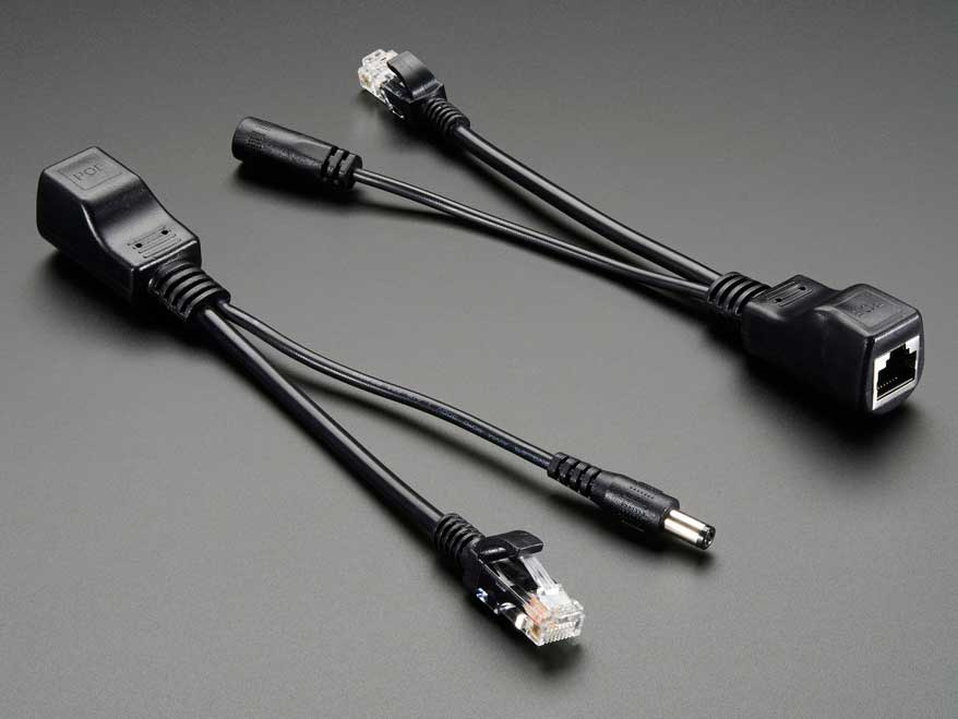
Passive adapters are very simple, and you will see them mostly as an RJ45 socket with pigtails for power and Ethernet. These adapters do not contain or require any circuitry, which also explains why they are the more inexpensive option between the two.

Photo of a passive PoE injector & splitter pair, sold on Adafruit

Active PoE (the real Power over Ethernet) on the other hand requires some negotiation between the two devices, called the PSE (power sourcing equipment) and the PD (powered device).

There are several PoE standards. 802.3af, 802.3at and the newer 802.3bt. The difference is mainly in the maximum power is made available to PDs:

  • 802.3af – 15.4W
  • 802.3at – 30W
  • 802.3bt – 60W to 100W

802.3bt was just ratified in the last year (2017). In the time span before the 802.3bt standards was ratified (~8 years!), some companies like Linear Technolgy & Cisco Systems took it upon themselves to find other means of carrying up to 60W. The result was LTPoE++ and UPOE, an evolution of the existing 802.3af/at standards, but may not be compatible with the final standard arrived at by committee.

Mode A or B

The Cat5 cable has 8 wires, forming 4 twisted pairs. For 10/100Mbps, only 2 pairs are used: pair 1/2 for Tx and pair 3/6 for Rx.

The modes refer to how power is delivered to the device:

  • Mode A: pairs 1/2, 3/6
  • Mode B: pairs 4/5, 7/8

PoE mode A & B wiring diagram

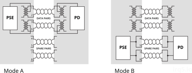
Mode A uses the data pairs for power. This mode is well suited for very old cabling which didn’t connect all 4 pairs end-to-end. You might see some manufacturers calling this mode End-span wiring. To carry power over the same data cables, phantom power delivery is used (more on this later).

Mode B uses the unused (or spare) pairs for power. You might see this being referred to as Mid-span. This type of wiring is easier because it knows the pair is not carrying any data and thus can be wired directly.

Unlike mode A, mode B in this form cannot be used to carry power for Gigabit networks, because a Gigabit connection will require all 4 pairs for data transmission. Power must therefore be delivered via centre-tapped transformers, or what is known as phantom power. How this works is explained in a 1944 US Army video on telephone electronics.

Power Capacity

The committee decided that two pairs of Cat5 wire should only carry up to 30W of power; which two pairs will depend on whether mode A or B wiring is used.

For higher power capacity like 802.3bt (PoE++) or the non-standards-based UPOE and LTPoE++, the other 2 pairs will be paralleled up, making use of all 4 pairs to carry higher currents.

PoE wiring diagram for 4-pair based PoE

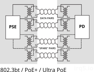
For Gigabit Ethernet (1000Mbps), because all 4 pairs are used to carry data, power (regardless of which pairs used) must be delivered via phantom power delivery.

Why use Active PoE?

In short, because it is safer.

It was designed with the consideration that not all network equipment can accept power, whether via the data pairs or spare pairs.

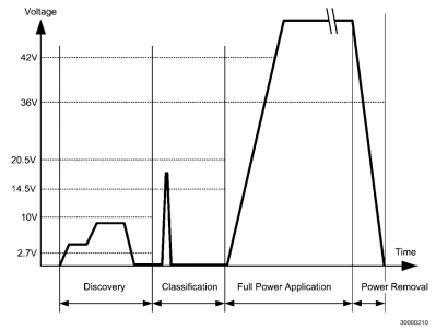
During the detection phase, the PSE will apply 2.7V to 10V to check for a known resistance. This voltage is low enogh and also for a brief period such that it wouldn’t matter if the device on the other end is shorted. A device that was not designed for PoE would thus never see any higher voltage beyond the detection phase.

Graph depicting voltage vs time during various PoE phases

In contrast, passive PoE makes the full voltage and current available on the data/spare pairs. If the remote end is using a magnetics configuration that shorts out the centre taps, the 30W of power would just melt the port (one would assume).

Integrated PSE controller chipsets will also contain features like overcurrent protection, thermal cut-offs and surge protection, etc. which all contribute towards keeping your PDs safe from harm.

Finding Low-Cost PoE Hardware

It was quite a daunting task, trawling AliExpress for PoE injectors & splitters. The description or specifications for items are also not accurate; it’s like finding a USB cable listed as capable of carrying 2A when in fact it does not.

While passive injectors are the cheapest option, most of them are not meant for Gigabit Ethernet. Recall that Mode B wiring is the easiest and most low-cost method for building a passive device, and that is what you will mostly find. This wiring configuration does not pass through all 4 pairs and thus cannot be used for Gigabit.

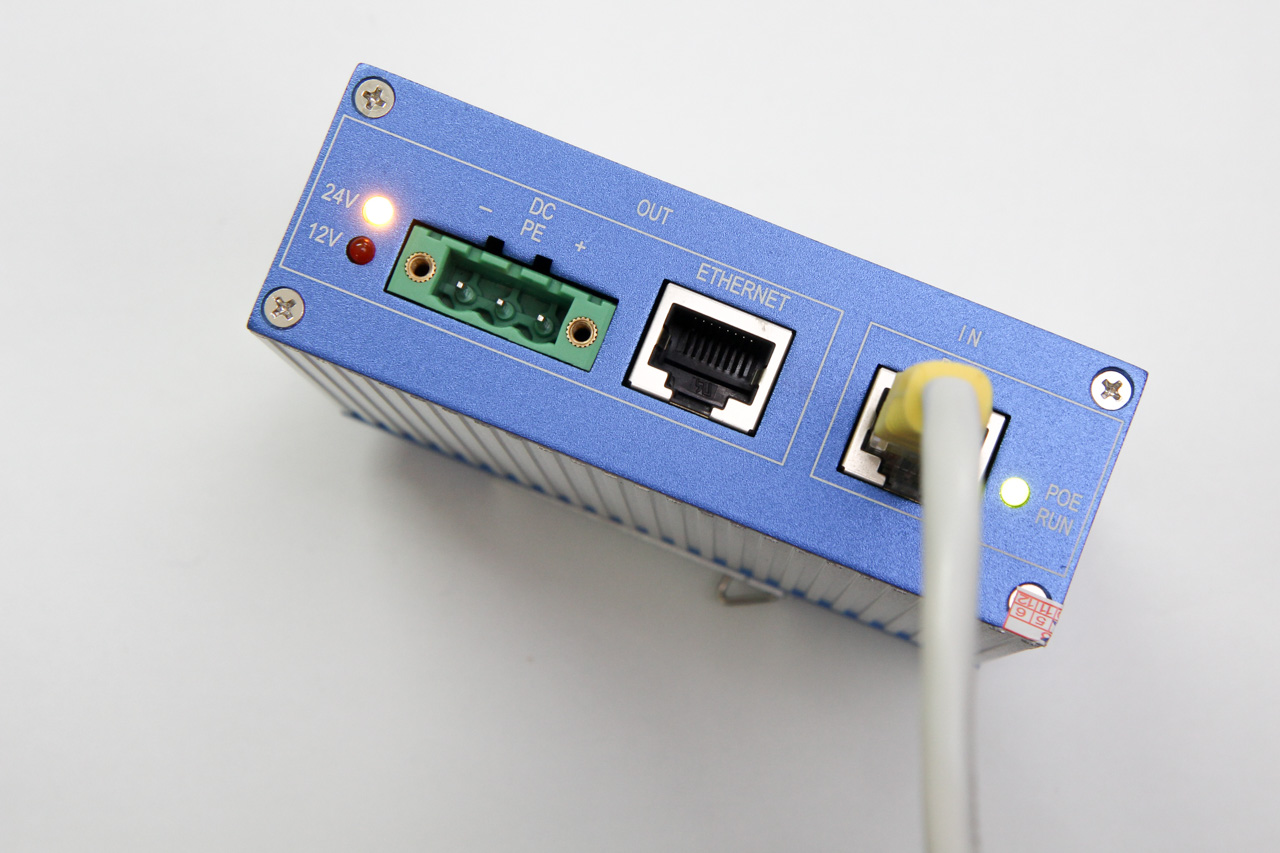
Most active PoE splitters output 12V, or 5V via USB. This is largely due to the fact that these devices were meant for IP cameras, which operate at that voltage. If your target device uses a non-standard voltage, you will have difficulty finding a suitable (and yet low-cost) splitter.

Here’s a list of hardware I’ve found; which one is suitable for you depends on your requirements:

  • Do you need 1000Mbps, or just 10/100Mbps would suffice?
  • What voltage does your target device require?
  • How much power does it require? 13W, 30W?

Continue reading

PCBWay PCB Review

PCBWay is a PCB manufacturer that prides itself on quick turnaround. You can learn about CNLohr’s sucess story here. They also offer detailed tracking of your order’s progress on their website.

They have reached out to me and kindly offered to sponsor the boards for this particular project, which I will be talking about in the coming weeks. As the cost of these boards were more expensive (compared to their “normal” orders), I had to pay for shipping myself.

With each PCB project, I find more and more methods of testing PCB manufacturers. This time, it’s with a PCB that is inserted directly into your USB socket.

project PCBs

The requirement for such a board is 2 mm thickness. The USB connector size is standard, so the usual 1.6 mm PCB thickness isn’t going to work unless you pad the connector area.

Also, I opted for gold fingers on the USB connector contacts. This is usually done for contacts on the board edge that will be inserted into some mating connector (like PCI cards and USB connectors such as this).

They also offer matte black & matte green colors. I haven’t seen matte colours being offered at other board houses so far. I would have loved to try them out, but that would have bloated the cost beyond my comfort level.

Order Process

The order flow for PCBWay is a bit different because you submit your gerbers without making payment first. This allows their engineers to take a look at the design before you actually pay.

Most other systems I’ve used are largely automated. After you submit your gerbers, they typically don’t expect any problems and so they collect payment from you first.

I uploaded the gerbers on the 8th Aug and I tracked my order progress online. Their website allows you to track the detailed progress of your board as it moves along the manufacturing process. For small runs like this one, it is not crucial but if you were doing a large project with panels of many boards, this would definitely be handy.

table of PCB production processes and their completion times

They started manufacture 2 days later (on the 10th) and completed everything by 12th. It was not until the 14th that they actually shipped the boards out and provided me with a tracking number.

Here’s a summary of the timeline:

  • 08: Gerber files submission
  • 10: start of PCB manufacture
  • 12: boards completed
  • 14: boards shipped (via registered post)
  • 24: boards received

Continue reading

Making USBasp Chinese Clones Usable

I don’t have any dedicated programmers. I have been programming Atmel chips using the USB-to-serial bitbang method.

Recently, I thought I’d get one because doing a re-programming cycle is taking quite a bit of time (a disadvantage of serial port bitbanging).

A popular one on Aliexpress seems to be this “USB ISP” one, so I bought one. I chose this one because it has a nice aluminium case, and a pinout diagram imprinted on the case, which is handy. After having so many one-off projects with bare PCBs collecting dust, I now appreciate the importance of having projects in their own box or case.

USB ISP programmer with aluminium case

While it has “USBasp” in the item name, it turns out that this was not a USBasp device, and getting it to work like one takes some effort.

It identifies itself as a zhifengsoft HID device when I plug it into Linux:

usb 3-1: new low-speed USB device number 3 using ohci-platform
usb 3-1: New USB device found, idVendor=03eb, idProduct=c8b4
usb 3-1: New USB device strings: Mfr=1, Product=2, SerialNumber=0
usb 3-1: Product: USBHID
usb 3-1: Manufacturer: zhifengsoft

avrdude does not recognize the device, even after creating an entry with the corresponding vendor/product ID. This particular device was designed to work with their Windows-based UI called ProgISP and will not work with avrdude.

And apparently you can’t just take the USBasp firmware and flash it into this device, because the circuit is somewhat different.

After some research based on the PCB markings, I found these sites that talk about them:

Disassembly

Disassembling the device is simple. While grabbing the side of the case, firmly push the USB connector inwards and the board should slide out the other end. You can then gently pull the board out by the IDC connector.

Disassembly how-to photo

The programmer seems to be based off of the popular USBasp programmer, but modified somewhat (to what end I’m not sure). It lacks some features offered by other USBasp programmers, like the ability to control the target’s clock, or to use 3.3V for certain targets. But at $2 with a nice aluminium case, what more can you ask for?

It’s powered by an ATmega88 (I read that older versions were based on ATmega8). The markings on the board indicate that this is a MX-USBISP-V4.00. You can ignore tHe date because it was never updated; the older V3.02 also has the same date. While the GreenPhotons blog was talking about V3.00, I have verified that this version suffers from the same issue.

USBISP programmer, with aluminium case

USPISP PCB rear

Note that there are provisions on the PCB to add a voltage regulator, and the PCB link marked “C” can be cut to separate USB power from the rest of the system. Link “D” can be cut if you wish to disable target power. However, none of these options were used.

The crucial difference with this clone is that the USB D- pin is additionally connected to PD3, shown here highlighted in blue:

Clone difference in schematic view

However, in the USBasp’s main() function, PORTD‘s data direction register was initialized like so:

  /* all outputs except PD2 = INT0 */
  DDRD = ~(1 << 2);

This causes the USB D- line to be actively driven from PD3, thereby impeding communication to/from the USB host.

The rest of this post will talk about (1) correcting this problem in USBasp, and (2) uploading the firmware into your zhifengsoft programmer.

Continue reading

Raspberry Pi Zero Wireless

On the 5th birthday of the Raspberry Pi last week, the foundation announced a new addition to the family — the Raspberry Pi Zero W. The W stands for Wireless.

I got my hands on one, from the fine folks at Pimoroni. (And no they didn’t pay me to say this.)

The Pi Zero W board

It has the same specs as the Raspberry Pi Zero, namely the 1GHz single-core CPU and 512 MB of RAM. It still has the two micro USB port — one for power and another for OTG, which means you can get it to behave like USB devices when plugged into a PC. The big difference is that they have added WiFi and Bluetooth capability to this small board by squeezing some space out from between the processor and the power circuitry. The size of the board and the placement of connectors remain the same, even the test points on the back.

I’m excited for anything that has processing power, HDMI connectivity and WiFi.

WiFi + Bluetooth

BCM43438 wireless chipset

The 802.11n WiFi and Bluetooth 4.1 functionality comes from the Broadcom BCM43438 (now known as the Cypress CYW43438). This is the same chipset that was used in the Pi 3. The wireless chipset connects via SDIO, so your network traffic does not have to contend for the USB bus bandwidth.

Continue reading