Raspberry Pi Zero as Multiple USB Gadgets

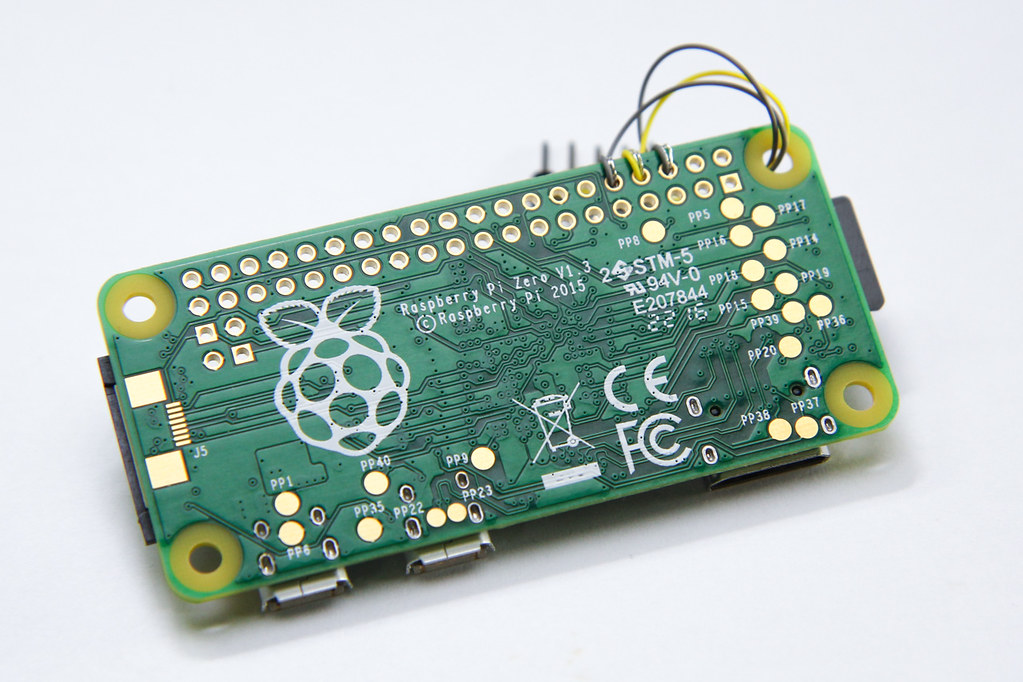
In case you haven’t heard, the Raspberry Pi Zero is the smallest, most low-cost device in the Raspberry Pi family, but it’s also the hardest to find. It has two Micro-B USB ports, one for power and another functions as a dual-role USB OTG port.

Raspberry Pi Zero, back side

One of the more interesting uses for the Raspberry Pi Zero is to get it to behave as a USB device, just like your USB flash drive, for example.

There have been several guides written already, such as the Adafruit one, but most of them were based on the old kernel gadget drivers, like g_serial and g_ether. It still works, but not as flexible and likely to be deprecated in future.

Continue reading

MIDI to USB (Serial) Converter

MIDI is actually just serial data at 31,250bps in 8N1 format that is transmitted over a 5-pin DIN cable. This means you can receive MIDI data from your musical instrument using a serial port, or an FTDI cable.

Receiving MIDI data over the FTDI cable doesn’t magically turn your USB serial device into a MIDI device – you need to be running a software bridge or a driver that pretends to be a virtual MIDI device emitting these messages. For this purpose, I shall use the Serial MIDI Converter from SpikenzieLabs.

I’m using Mac OS X 10.6.6 and the latest Java update, so I didn’t need any extra JAR files.

Wiring It Up

The circuit is relatively simple – you need the DIN socket, an opto-isolator, 2 resistors, and optionally a diode. In my case, parts came from a scrap bin, so I used a 330 ohm resistor instead of a 220 ohm for Rb and a 1K for Rd instead of 280 ohms. For the opto-isolator, element14 had some non-RoHS CNY17-2 on sale, so I just used that.

Note that the RXD output is only meant for interfacing with a TTL circuit like an FTDI chip/cable or MAX232 transceiver, not the RS232 serial port directly.

You can find the same circuit diagram (with different values & parts) in the official MIDI Electrical Specification Diagram.

Continue reading

RS232 converter + TTL-232R-3V3

If you’re into microcontrollers like me, you should have an FTDI breakout board or the more handy FTDI TTL-232R-3V3 cable. This cable integrates an FTDI USB-to-serial chip and terminates into a 6-pin header, with TTL in/outputs, ready to be interfaced to any microcontroller.

Recently I had to talk to an RS232 port. The voltage used by the RS232 port is anywhere from 7 to 15V (typically), and uses both positive and negative voltages, which cannot be directly interfaced with TTL. Most of my university friends who took microcontroller class previously bought an RS232-to-USB converter, since that’s what the trainer board (evaluation board) uses, but not me. So what should I do now?

Using a MAX232 (actually a HIN232) chip and 5 capacitors, I followed the recommended application circuit to build a level shifter. I laid out the circuit on a veroboard with a 6-pin header on one end for the TTL-232R-3v3 cable, and a 2×5 header for the RS232 port.

Since I ripped out many old computers with those serial port headers I decided to use it. The pinout for the RS232 port header is available in many motherboard manuals, including mine. The only pins (usually) of interest are circled. The pins are 2, 3 and 5 for receive, transmit and ground, respectively.

Continue reading