Boot-time Device Tree Overlays with U-Boot

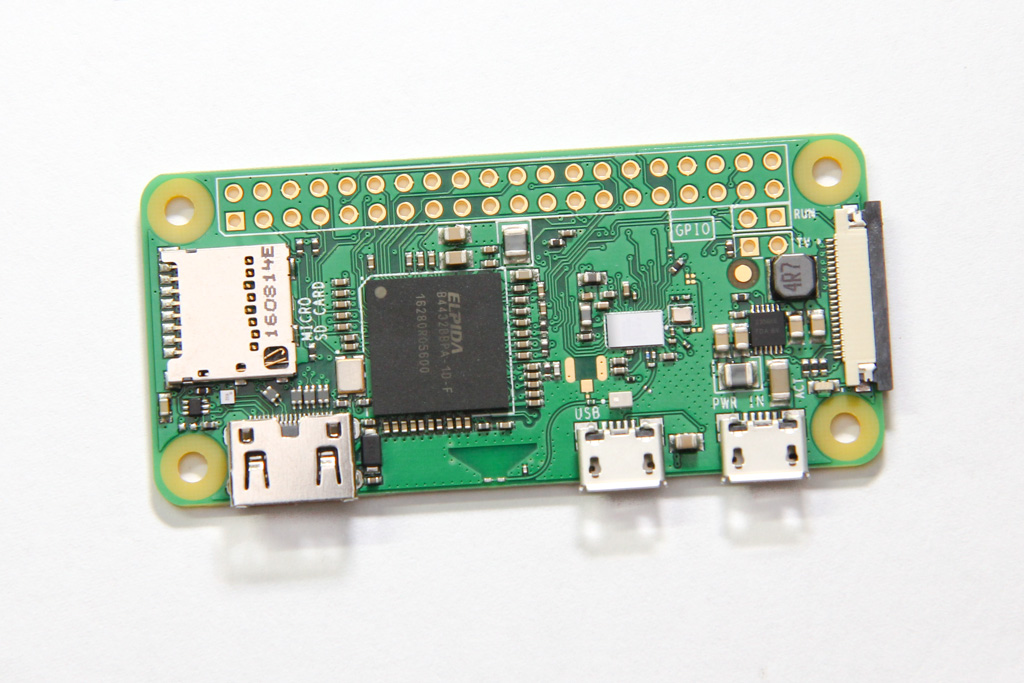
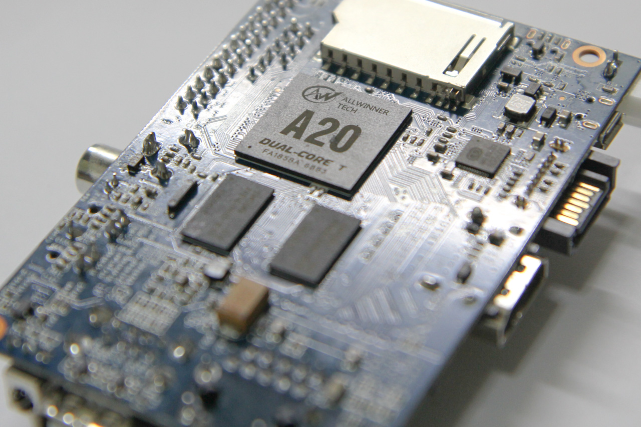
I bought a Banana Pi some time ago and have been using it as my go-to ARM box. Among the single-board computers I have, this Allwinner A20-based platform has the fastest CPU.

Similar to the (old) Raspberry Pi, it has a 26-pin GPIO header on one side that sports the same layout. This means that the 5V, 3V3 and I2C pins are the same as where they would be on the Raspberry Pi.

Device Tree & Overlays

On embedded systems, the Device Tree helps the kernel understand various peripherals that are connected to the board and how to initialize them. These hardware might be things like LDO regulators, various controllers, GPIO, etc which are generic, but yet needs certain configuration that should not be hard-coded into the kernel. To understand more about device trees I recommend you start with the Raspberry Pi documentation on this topic. There are more links at the end of this article.

To support Pi HATs and other non-HAT accessories, the Pi added a dtoverlay configuration parameter in the config.txt file. This allows you to specify, at boot time, Device Tree Overlays, which modify the board’s base device tree to specify additional peripherals like I2C devices, or to configure GPIO pins for certain purposes. The BeagleBone also has a similar mechanism to support its add-on boards via Capemgr. These mechanisms enable non-technical users to easily modify the device tree by simply editing a text file or running a command. Neither of these have been adopted into mainline Linux, so there is no provisions for doing quick overlays on other boards yet.

Fortunately for us, device tree overlay support has been merged into U-Boot, and the Banana Pi uses U-Boot for booting Linux. This means that U-Boot can perform the merging of device tree overlays with the base device tree, and pass the entire Flattened Device Tree (FDT) structure to the kernel during boot-up.

Before we get started, you will need the i2c-tools and dtc-overlay package, and the U-Boot source code for the mkimage tool (you did have to compile U-Boot for your Banana Pi right?)

Creating the Overlay

For this example, we will be attaching an INA219 current sensor to the Banana Pi over I2C. The kernel has drivers for this sensor in its hwmon subsystem and provides an easy way of reading values for us.

INA219 current sensor breakout board

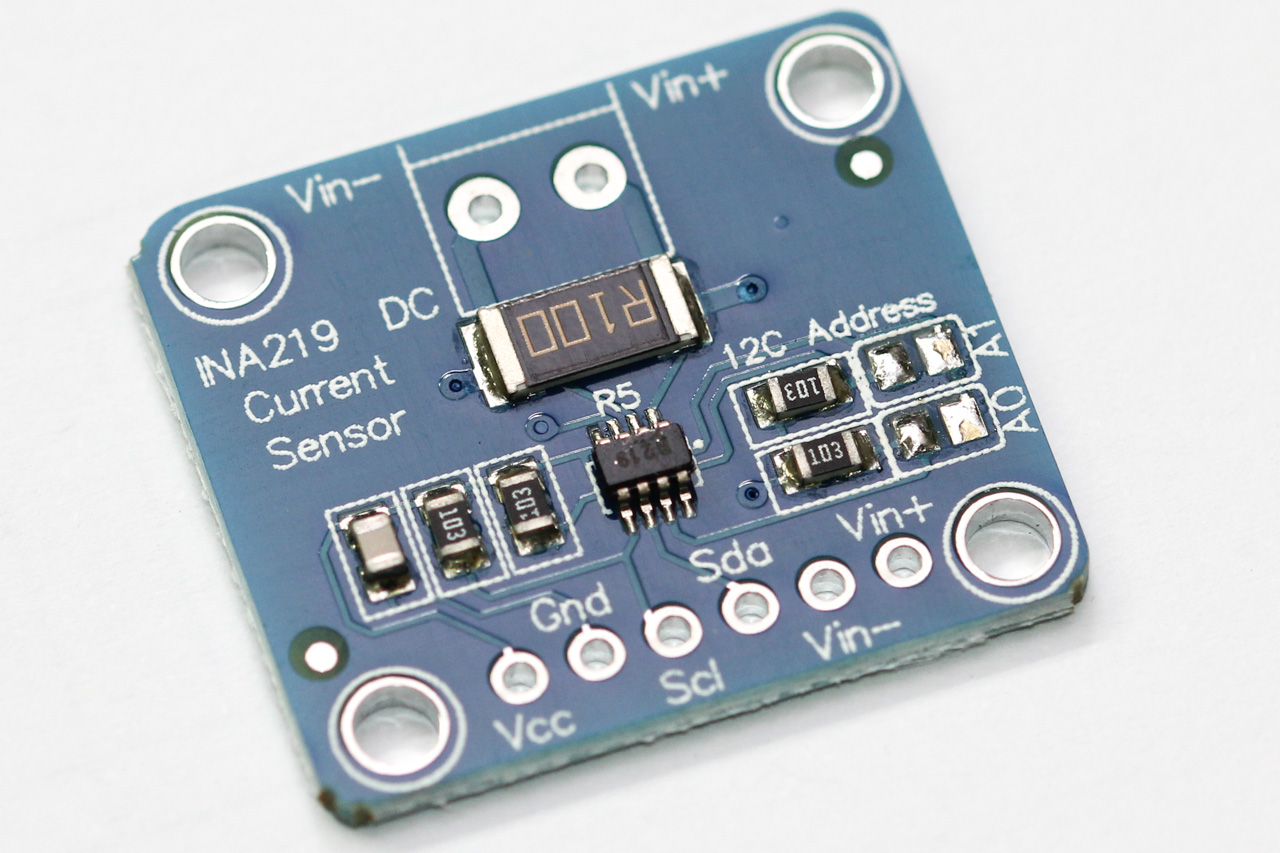
The default I2C address on most INA219 breakout boards is with the address lines A0 and A1 grounded, giving it an address of 0x40. Also note that the shunt resistor is marked with R100, which denotes 0.1 mΩ or 100,000 µΩ.

My Banana Pi has 3 I2C buses:

$ i2cdetect -l
i2c-1   unknown         mv64xxx_i2c adapter             N/A
i2c-2   unknown         sun4i_hdmi_i2c adapter          N/A
i2c-0   unknown         mv64xxx_i2c adapter             N/A

We will try scanning each of the buses, and the one with device 0x40 will likely be the bus that is exposed via the GPIO headers. We can do this using i2cdetect:

# i2cdetect -y 1
     0  1  2  3  4  5  6  7  8  9  a  b  c  d  e  f
00:          -- -- -- -- -- -- -- -- -- -- -- -- --
10: -- -- -- -- -- -- -- -- -- -- -- -- -- -- -- --
20: -- -- -- -- -- -- -- -- -- -- -- -- -- -- -- --
30: -- -- -- -- -- -- -- -- -- -- -- -- -- -- -- --
40: 40 -- -- -- -- -- -- -- -- -- -- -- -- -- -- --
50: -- -- -- -- -- -- -- -- -- -- -- -- -- -- -- --
60: -- -- -- -- -- -- -- -- -- -- -- -- -- -- -- --
70: -- -- -- -- -- -- -- --

The last parameter to i2cdetect specifies the bus number, which is 1 in this case. We can see here that the INA219 has been correctly wired and detected, as it shows up in the I2C bus scan.

We now need to find out which device tree node this bus corresponds to:

$ readlink /sys/class/i2c-adapter/i2c-1/of_node
../../../../../firmware/devicetree/base/soc@1c00000/i2c@1c2b400

In order to figure out the symbolic name for this I2C bus, we can grep from the kernel’s live device tree, parsed with the help of the dtc utility:

# dtc -I fs /proc/device-tree | grep 1c2b400
...
    i2c2 = "/soc@1c00000/i2c@1c2b400";

Continue reading

Raspberry Pi Zero Wireless

On the 5th birthday of the Raspberry Pi last week, the foundation announced a new addition to the family — the Raspberry Pi Zero W. The W stands for Wireless.

I got my hands on one, from the fine folks at Pimoroni. (And no they didn’t pay me to say this.)

The Pi Zero W board

It has the same specs as the Raspberry Pi Zero, namely the 1GHz single-core CPU and 512 MB of RAM. It still has the two micro USB port — one for power and another for OTG, which means you can get it to behave like USB devices when plugged into a PC. The big difference is that they have added WiFi and Bluetooth capability to this small board by squeezing some space out from between the processor and the power circuitry. The size of the board and the placement of connectors remain the same, even the test points on the back.

I’m excited for anything that has processing power, HDMI connectivity and WiFi.

WiFi + Bluetooth

BCM43438 wireless chipset

The 802.11n WiFi and Bluetooth 4.1 functionality comes from the Broadcom BCM43438 (now known as the Cypress CYW43438). This is the same chipset that was used in the Pi 3. The wireless chipset connects via SDIO, so your network traffic does not have to contend for the USB bus bandwidth.

Continue reading

Raspberry Pi Zero as Multiple USB Gadgets

In case you haven’t heard, the Raspberry Pi Zero is the smallest, most low-cost device in the Raspberry Pi family, but it’s also the hardest to find. It has two Micro-B USB ports, one for power and another functions as a dual-role USB OTG port.

Raspberry Pi Zero, back side

One of the more interesting uses for the Raspberry Pi Zero is to get it to behave as a USB device, just like your USB flash drive, for example.

There have been several guides written already, such as the Adafruit one, but most of them were based on the old kernel gadget drivers, like g_serial and g_ether. It still works, but not as flexible and likely to be deprecated in future.

Continue reading

Netbooting Your Raspberry Pi

A very long time ago, I set up and played around with diskless machines. These are basically PCs can boot up an operating system fully without hard disks. All the operating system files come from a server on the network. It was amazing (well, to me at least)!

Back then, Ethernet cards used to have a DIP/PLCC socket, which allowed you to insert an EEPROM on which you burn a boot ROM. Fortunately I didn’t have to do any of that because the network cards at that time already came with PXE ROMs built-in, just as they do today. To activate this, you just need to select the network card’s option ROM in the boot order, or make it higher up in the boot priority.

3Com network card with boot ROM socket marked

As part of the boot process, the network card will request an address from the DHCP server, which also tells the client where it can find the TFTP server with the next boot stage. The ROM will download this file from the TFTP server and start executing it.

That’s how Linux ultimately gets started from the network.

An announcement was made recently on the Raspberry Pi blog that you can achieve total network boot, just like on the PC, without any SD cards.

Continue reading

Cloud-Enabling a Bathroom Scale

Last week as I was making my rounds at the supermarket, I came across this digital bathroom scale on sale. With some membership card, the discount was almost 50% and at S$16, I thought that was a pretty good deal. It is “wireless” in that it has a separate display unit that could be detached from the scale itself. This bathroom scale had “HACK ME” written all over it.

It turns out that this bathroom scale is the EB9121 made by a Chinese (OEM?) company called Zhongshan Camry Electronic Co. Ltd (or simply Camry). The box specifically mentions that it uses infrared for transmission, and given that I had some experience looking at IR signals, I thought it would be rather straightforward.

Continue reading