Some painters came over to give my house a new coat of paint for the new year, and in the process wrecked my vintage bathroom mirror. We have what’s called a tilting mirror or pivot mirror in the bathroom area, which we have been using for at least 50 years in the household. We adjust the mirror tilt every day for decades and it has never broke. This style of mirror is quite uncommon these days, perhaps because it has gone out of fashion.
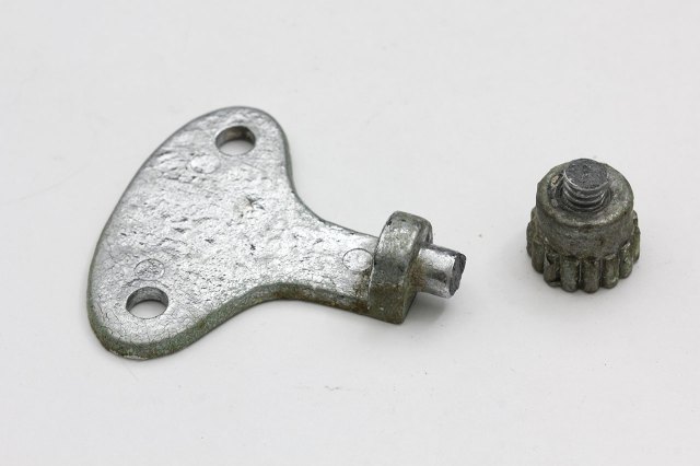
Looking at the damage, it was clear they forcefully tried to remove the nuts securing the mirror and it just snapped off. The other bracket on the opposite side broke off too, but at a different location. I’m no metallurgist but it looks like the part was made from cast iron or something, and therefore quite brittle. For years now I didn’t dare to dismantle the mirror for exactly this reason: the thumbnut loosens up till a certain point then refuse to go further, which is also why I left it in place. I have already removed everything I could for them – toothbrush holders, any hanging towels and racks. Anything else still left on the wall is obviously not removable, or I would have done so already. But these fuckers took it upon themselves to try to remove the mirror when I left them alone for an hour. To say I was very pissed is an understatement.
When they told me they broke the mirror, I thought they had shattered the mirror glass. I was at least a little hopeful when I saw they had placed the mirror under the sink. Still, I was at a loss of how to fix the mirror, until the idea of leveraging 3D printing hit me days later. I’ve known about it since the MakerBot days (and it was a hot topic at maker faires) but since I don’t have a 3D printer or easy access to one, it was just something I didn’t care too much about.
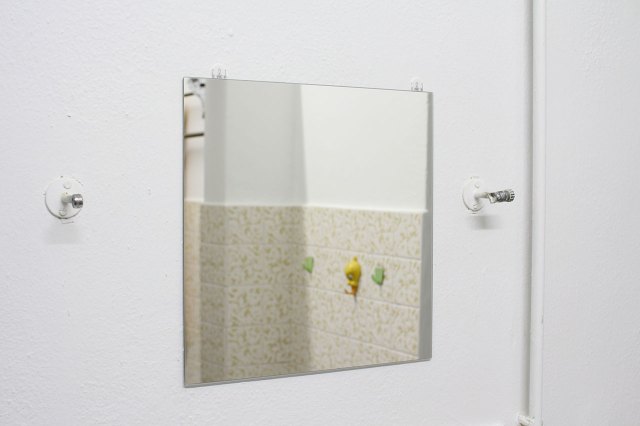
What is in its place now is a piece of IKEA BLODLÖNN, which I have used 3M Command strips to temporarily hold in place, while I tried to learn enough FreeCAD to design a replacement bracket. Buying IKEA was the cheapest option, and I had an inkling that learning FreeCAD from scratch was going to be a steep learning curve, so we needed something to use in the meantime (we kept looking up but finding ourselves staring at a blank wall). You can see the metal supports arms for the tilting mirror are left intact on the wall, but now painted white1.
Follow me as I detail how difficult it is for someone with zero experience like myself to learn FreeCAD, which hopefully inspires you not to give up, and the final results of my journey.
Learning FreeCAD
I chose FreeCAD (latest version 0.20 at the time of writing) simply because it was free and open-source. I knew nothing about designing in CAD for 3D parts, so I turned to YouTube videos like most people these days. YouTube channel MangoJelly was very helpful in this regard and I learned quite a lot by going over their videos and tutorials. I have also been watching Clough42 videos prior to this and the only thing I learnt about CAD modeling was sketching a 2D shape then extruding it to make it 3D. He makes quite a few walkthroughs of using Fusion 360 to design parts he needs.
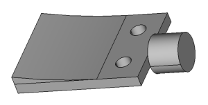
For 3D CAD, you need to have some rough idea of how your object will be constructed, and you can only know how if you know the tools within FreeCAD and how to use them. My initial attempt was to first draw the bracket with the mounting holes, then adding a slope behind it for a thicker support in order to punch an M6-sized hole through it for the screw. However, I had difficulty trying to place the screw nub at the right place, and the split between the slope and base piece had a seam, so it couldn’t be treated as a single face to create a hole from. And all this was even before I could add the side wall lip to support the mirror glass. It was so frustrating trying to “assemble” my idea in FreeCAD that I just gave up, rage quit. Here’s what I ended up with before I gave up:
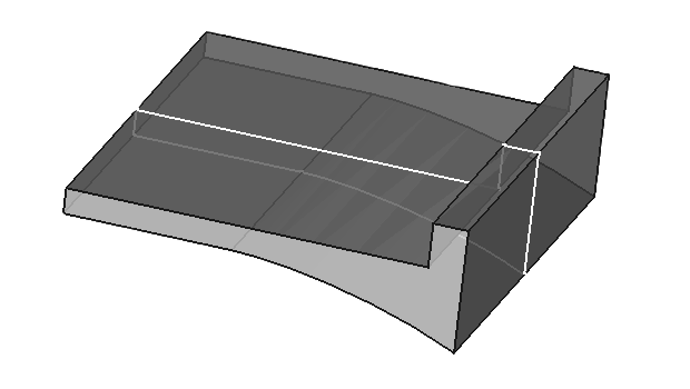
I realized that nobody else was going to solve this for me, so I persevered and came back to it again later after some weeks. Several YouTube tutorials later, I had the bright idea that I should actually draw the entire curved base with the side wall as a single side profile, then extrude (or “pad”) that to form the base. Since the screw hole should be in the center, I made the pad “symmetric to plane”, which means it extends outwards from the center. After that, I just needed to add the screw nub to the side wall, and I did that by making sure the side wall is against the XZ plane (think of it as the origin 0,0,0) so the nub would be easy to align.
It finally felt like I was making progress, and that I might actually be able to pull this off.
And that was ultimately what I used as the base model for my design. I used fillets to round the edges and added a few more finishing touches. It all seems so easy and fulfilling now when you know what you’re doing. If you want to see my first attempt, you can look it up in the Git history.
“Brittle” Models
Alas, my woes with FreeCAD were not over yet. The design is usually an iterative process, and in FreeCAD you’re always building on top of previous structures/steps. So for example, when the base profile is sketched out, it’s a 2D shape, then that gets padded out to form a 3D shape. After you have that shape, you may want to drill holes into the surface so you add holes onto it. When you suddenly think of some design aspect to add/tweak (which no doubt will happen since you are still inexperienced) and go back to the previous step(s) to modify it, FreeCAD seems to re-generate everything from that step onwards. In the process, it might decide to shuffle all the existing vertices and edges. This process is non-deterministic, as are all the faces and edges it generates; they are just called Edge1, Edge2… Now the holes you previously placed on Face5 may end up elsewhere, like on the underside or even the side wall of the shape because that’s now called Face5. I think this is referred to as the topological naming problem. Right before I published this post, YouTube recommended me a video and it demonstrates and explains this problem visually, and it also affirms my thoughts on this below.
I don’t know if other CAD software work this way or I’m doing it wrong, but it is extremely annoying, and not to mention, time-consuming. If you edited something in step 1, you now need to tweak steps 2 through 10 to make it work right. This problem is further compounded because fixing something in step 2 might require more changes in step 3 and so on. What’s worse is this happens even when you simply open a sketch and close it without making changes, FreeCAD may still re-generate everything anyway. A real example was me adding fillets to the base shape, then adding holes, then adding a fillet to round the hole openings. All of these features kept shifting and disappearing and I had to keep updating them.
One way I try to prevent this, if I have the foresight or remember to do it, is to add parameters (or “constraints”) to the sketches. This can be things like the width of the part, thickness of the walls, or size of the holes, etc. I can then modify these constraints under the inspector tab and that would not trigger the re-generation and re-computation of the shape.
However there’s another problem: I wanted to print a 1:1 copy of the part to physically verify the dimensions before 3D printing. This is what I usually do for my PCBs too before production. Forums told me that the TechDraw workbench was the right tool in FreeCAD for this, so I used it select a 2D view to add dimension markings to the holes and various important parts. This would allow me to iterate on the design if the physical part didn’t match, and after you have printed several sheets of paper, it would be good to know which version this physical printout corresponds to.
Even when I modify the sizes via the constraints without opening the sketch, I come back to the TechDraw view and now the dimensions have shifted all over the place, leaving you with a mess like this:

So my workflow here was to print the page, match up the part on paper to see if it fits, alter the hole position/spacing, go back to TechDraw to find the dimensions all messed up, delete and re-add the dimensions to the newly re-generated edges and holes, print and repeat.
I really don’t know how anyone can use FreeCAD in a professional setting; it just feels very unpolished and/or buggy. I thought I was a n00b, but it turns out that Thomas Sanladerer recently tried out FreeCAD and had a similar experience, despite being a pro user who has had experience with various CAD software. If someone who isn’t a beginner to CAD is struggling with getting FreeCAD to “work”, then you can imagine what I had to deal with to get the model designed exactly the way I wanted it.
Maybe jumping from zero experience directly into FreeCAD was a mistake and explains why I rage quit after a week. The software is very unforgiving and breaks very easily.
Part Design
I didn’t replicate the original bracket design as-is because I don’t think it would be that strong when 3D printed, compared to the original all-metal part. So I did what I knew could be done in 3D printing: a threaded hole that receives a thumbscrew. The M6 thumbscrew and threaded inserts were just bought off AliExpress.
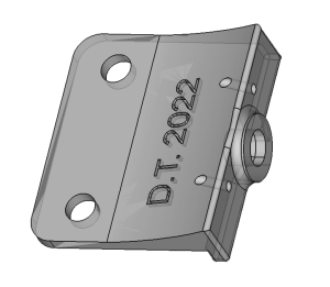
I made the back curved near the screw hole to give it more material, making it sturdier. Again, I don’t know if this was really necessary or how much printed material is required, but the mirror is made of glass and it’s quite heavy. The last thing I want is for this part to break and destroy the mirror, for real this time.
I added holes for a safety wire, because now it’s possible for someone to accidentally undo the thumbscrew and the whole mirror might become dislodged. Although thinking about it now, if the bolt were to be removed, the mirror would probably smash into the back wall and shatter.
I imprinted my initials & date on the back, so that one day when the mirror is disassembled again, someone would find it and know that I fixed this damn thing in 2022/23.
I was pretty satisfied with this final iteration. It looks like a professionally designed piece after adding fillets everywhere (which I also learned from Clough42), and it was really an achievement for me to get this far with FreeCAD.
Printing & Assembly
As I didn’t have a 3D printer, I chose to have it printed at JLCPCB, where I usually send my PCB orders. I chose to print the bracket out of Nylon PA-12 using MJF (Multi Jet Fusion) because I think it’s stronger, again based on the Clough42 videos I’ve watched.
There’s something magical about seeing your CAD’ed object materialize in its physical form for the first time. I quite like the matte sand-blasted finish on the Nylon-PA12 material.
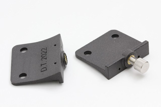
I had difficulty trying to melt the threaded inserts into the nylon part. I don’t really have the proper tooling for inserting these threaded inserts, but watching this TriMech video showed me it was possible on nylon parts and the insertion looked like it required quite a bit of force. So I just turned up the heat to 370°C and pressed down on it pretty hard.
It could be a combination of these issues, but without further experimentation and more re-prints I can’t say for sure:
- too small hole size: it was supposed to be 7mm, but after printing the hole only measured 6.8mm, so the heated material can’t squeeze out properly
-
Nylon-PA12 doesn’t “melt” easily, so higher heat is required
-
lack of proper tools, making it difficult to transfer heat efficiently into the heat-set insert
Here’s how the 3D printed bracket looks like when mounted onto the back of mirror glass. It looks like a pretty good fit; it’s designed to have some tolerance around the holes and against the side of the glass.
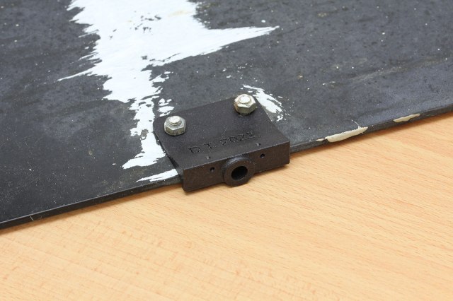
The white paint streaks left on the back of the mirror tells me that the paintbrush kept brushing up against it and they were trying to avoid that. They could have simply wrapped it in plastic, which is what they did for everything else like wall outlets, bathroom tile edges and the floor skirting, but I don’t know what possessed them to try removing the mirror entirely instead. All of this could have been easily avoided.
End Result
Here is the repaired mirror back on the wall, (almost) the same way it was before it was damaged. The 3D printed brackets fit the mirror nicely, and they stand out being black instead of silver. The mirror pivots like before, and the thumbscrews don’t seem to work themselves loose.
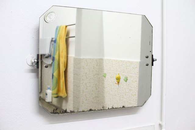
There’s just something about the chamfered corners cut into the mirror glass, and that worn away blackened edges of the mirror that show its age. I have an affinity for preserving nostalgic old things, like this mirror, and I’m glad to be able to fix it. I’m still pissed though, have I mentioned that?
The one good thing that came out of this was forcing me to pick up a new skill.
Conclusion
When I submitted my CAD file for printing, I noticed that they also offered “SLM (Metal)”, which I guess stands for Selective Laser Melting. Perhaps for my next iteration I might be able to replicate the original metal bracket design as-is and have them print it. I have watched a video review of their SLM printing service and it seems to perform quite well. Using another similar service, their SLM part took a lot of force to break despite having a small cross-sectional area. It gives me confidence that the original bracket design is sturdy enough if it is printed in metal.
After dipping my toes into CAD and 3D printing, I’ve found more situations to apply it to, and have been designing more parts since, though sending it off for printing is still a little expensive and the design-print-debug cycle is rather long as I usually opt for the cheapest delivery method. Feel free to check out my GitHub repo for 3D parts if you’re interested.
If you’re new to CAD modeling, I’d suggest trying software other than FreeCAD first. The user experience is very bad for new users and that’s very off-putting, as I (and others like Thomas) have experienced. However, after having used it for a year so far, I’m getting used to its quirks and have gotten better & faster at modeling stuff.
I also recommend these YouTube channels, for 3D printing and CAD modeling, or if you’re just generally interested in all this stuff like me:
- Teaching Tech, uses Onshape quite often
- Clough42 for the Fusion 360 design videos
- MangoJelly Solutions, specifically for FreeCAD tutorials
- This was another thing that irked me: they painted over everything, like these metal mirror support arms and also over the screws of things that I have temporarily removed. They also painted over the brackets for blinds which I also removed, and after the paint hardened I can no longer twist to re-attach the blinds; I had to scrape those off. When I asked them about it, they told me it was for anti-rust protection, anti-corrosion and anti-whatever, but they also painted over plastic wall hooks which had some decorative colour pattern on them. Now everything is just white. Seriously, what a load of rubbish. ↩

Gentile Tan,
apprezzo molto quello che stai facendo e la tua passione per la conservazione di cose vetuste che ancora possono funzionare e dimostrare come le cose possono farlo anche se progettate in epoche dimenticate. E’ una cosa che piace anche a me e che spesso mi fa spendere molto tempo in cose che farebbero spendere poco se si acquistassero nuovamente anziché ripararle. Ma c’è qualcosa in più ed è il poter dire: ce l’ho fatta!
Non voglio criticare il modo come ha risolto tu, ma elencarti le mie perplessità ed i modi per ovviarvi.
Il mio primo timore è sul materiale che hai impiegato. A differenza del metallo, qualsiasi altro che si utilizza per la stampa in 3D è sicuramente meno resistente. Questo potrebbe essere risolto con un differente approccio ed una diversa costruzione. Visto che tu hai già delle copie ‘fedeli’ dei pezzi originali, potresti disegnare dei pezzi da studiare, per valutare se davvero hanno qualche vantaggio oppure no.
Il mio secondo timore sta negli inserti filettati ed il modo di applicarli che senza dubbio indebolisce il materiale di stampa 3D, Io preferisco studiare pezzi in cui posso inserire dadi con filetto da 6mm ma senza dover utilizzare il calore. Naturalmente i dadi vanno inseriti non spingendoli dalla parte del foro per il bullone, ma a 90 gradi dall’asse di inserimento.
Io uso quasi esclusivamente PLA e tu saprei bene che ogni layer si ..’attacca’ al layer precedente e successivo, ma formando un certo indebolimento. Ecco il perché dei miei timori. Dopo un po’ di tempo, a secondo del ‘verso’ in cui un pezzo è stampato, l’unione dei layer sottoposti a trazione tende a indebolirsi e in casi estremi a cedere e rompersi. A volte è sufficiente stampare il pezzo ruotandolo su di un asse, ma non sempre è possibile.
La prima compensazione alla mancanza robustezza, tenterei di ottenerla con un aumento degli spessori, almeno dove possibile. Se non fosse possibile mi rassegnerei a cambiare la forma del pezzo (un approccio diverso). Io credo che nel tuo caso non sia tassativa la ‘forma’ del pezzo, bensì la sua funzione. Farò un disegno e te lo manderò, ma proverò ugualmente a spiegarti cosa intendo. Ritengo che tu possa realizzare un pezzo con uno spessore maggiore, perché verrebbe comunque coperto dallo specchi stesso. Le viti di fissaggio dello specchio potrebbero così essere più lunghe e necessitare di essere strette con minore forza. Sul retro potresti realizzare delle cavità esagonali (forse lo hai già fatto) per alloggiare i dadi (meglio se con un piccolissimo sforzo). Veniamo ora al perno di rotazione, realizzato con le stesse viti necessarie al bloccaggio dell’inclinazione dello specchio. Penso che anche qui sarebbe meglio agire su dadi veri e propri (con filetto da 6 mm.) inseriti in cavità esagonali poste sulla parete opposta a quella dove entrano le viti di bloccaggio, che costituiscono anche l’asse di rotazione. Immagino che queste viti non abbiano bisogno di essere strette con molta forza, dato che lo specchio sarà sempre ‘bilanciato’, quindi ecco perché è sufficiente una manopola così piccola. Nella soluzione che ti suggerisco, avendo spostato l’asse di rotazione, l’equilibrio sarà alterato e sarà necessario stringere con un po’ più forza. Fammi sapere se sono riuscito ad essere chiaro oppure se come al solito ho solo confuso le idee.
Un gran saluto Umberto
Hi Umberto, thank you for the detailed comment! It is indeed fulfiling to fix things yourself.
Regarding the printing strength, it seems that the MJF process isn’t really like regular FDM printing and doesn’t suffer from the same layer lines weakness. If I had used regular 3D printing then I might need to worry about that. To be honest, at the time I designed this I was unaware of this issue, but fortunately it doesn’t affect this part.
Regarding the threaded inserts, I also thought that it would weaken the part, but according to tests performed they are quite strong
and the more important feature for me is they can be unscrewed and screwed many times over. You can watch this video from CNC Kitchen that tests this. My understanding is that in most cases you should just use threaded inserts; it’s a safe default option.
As for the part design itself, I have thought about the issues you mentioned too. But since I am not printing the part myself and I’m also new to this, I would like to aim for a design that is simple to model and will work on the first try, so I don’t have to re-design and order a new print, if possible. I don’t have the luxury to make multiple designs and experiments to test which design is more robust, my only requirements are that it has to be strong enough (based on “common sense”) and it has to work. Therefore, the shape is mostly the same as the original but made more squarish and I just added material near the bend where I think it might be weak. I also didn’t make hexagonal holes to capture the nuts, again because of simplicity.
Hi.
How can I send you some STL and JPG files? I will attach them here, but your website doesn’t give you them.
Greetings Umberto