PCBWay PCB Review

PCBWay is a PCB manufacturer that prides itself on quick turnaround. You can learn about CNLohr’s sucess story here. They also offer detailed tracking of your order’s progress on their website.

They have reached out to me and kindly offered to sponsor the boards for this particular project, which I will be talking about in the coming weeks. As the cost of these boards were more expensive (compared to their “normal” orders), I had to pay for shipping myself.

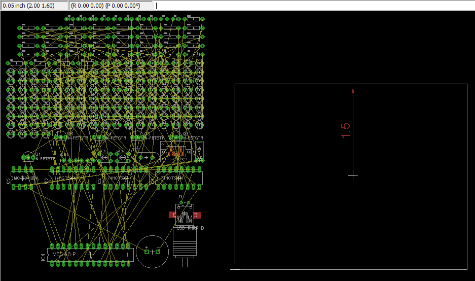
With each PCB project, I find more and more methods of testing PCB manufacturers. This time, it’s with a PCB that is inserted directly into your USB socket.

project PCBs

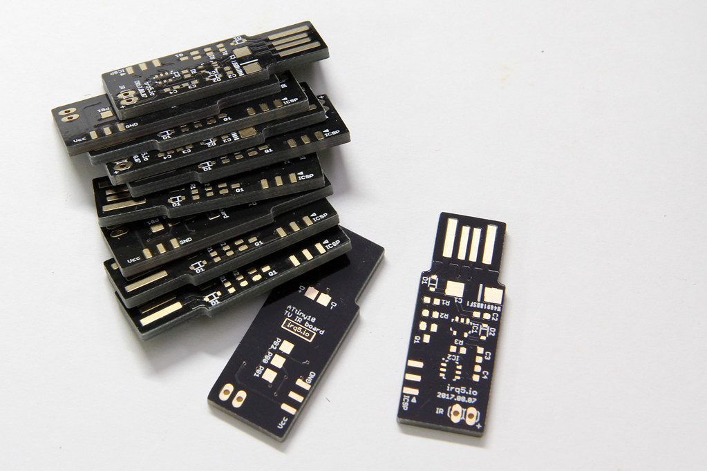
The requirement for such a board is 2 mm thickness. The USB connector size is standard, so the usual 1.6 mm PCB thickness isn’t going to work unless you pad the connector area.

Also, I opted for gold fingers on the USB connector contacts. This is usually done for contacts on the board edge that will be inserted into some mating connector (like PCI cards and USB connectors such as this).

They also offer matte black & matte green colors. I haven’t seen matte colours being offered at other board houses so far. I would have loved to try them out, but that would have bloated the cost beyond my comfort level.
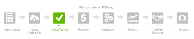
Order Process

The order flow for PCBWay is a bit different because you submit your gerbers without making payment first. This allows their engineers to take a look at the design before you actually pay.

Most other systems I’ve used are largely automated. After you submit your gerbers, they typically don’t expect any problems and so they collect payment from you first.

I uploaded the gerbers on the 8th Aug and I tracked my order progress online. Their website allows you to track the detailed progress of your board as it moves along the manufacturing process. For small runs like this one, it is not crucial but if you were doing a large project with panels of many boards, this would definitely be handy.

table of PCB production processes and their completion times

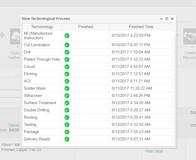
They started manufacture 2 days later (on the 10th) and completed everything by 12th. It was not until the 14th that they actually shipped the boards out and provided me with a tracking number.

Here’s a summary of the timeline:

  • 08: Gerber files submission
  • 10: start of PCB manufacture
  • 12: boards completed
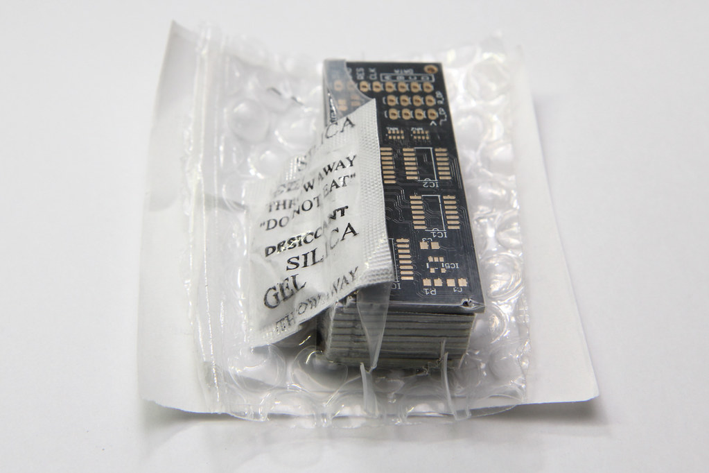
  • 14: boards shipped (via registered post)
  • 24: boards received

Continue reading

Seeedstudio Fusion PCB Review

Fusion PCB is a PCB service from Seeedstudio. They have been offering PCB prototyping service since I made my first board in 2011. It has recently been revamped a little, tweaking prices and options, as well as integrating an online Gerber viewer from EasyEDA. I was invited to give Seeedstudio’s revamped Fusion PCB service a try, and since I had some boards in the pipeline for manufacture, I thought why not?

You can configure various options for the PCB, such as board thickness, copper pour and surface finish. You can also make flex PCBs or aluminium for better heat sinking, as opposed to regular FR4. These options will of course come at a price. However, you can select various colours for your PCB at no additional cost.

The Boards

I ordered 2 sets of boards in total. I’ve decided to opt for an ENIG finish for the TIL311 display boards, just because it looks nicer in gold. The boards are manufactured with black solder mask, making the gold pads stand out better.

I’ll describe the display board in a separate post after I’ve assembled it. For now, here’s what 4 of the boards look like, component side up:

TIL311 display PCBs

Like most PCB prototyping services, they track your order by printing some kind of order identifier onto each PCB. Usually they try to put this identifier underneath a component like an IC so it gets hidden when the board is fully populated, but sometimes they put it somewhere prominent, like under your product name. On this board, the identifier sits under IC4 but for the other board, it was under the product name.

The PCBs arrived in a shrink-wrapped bubbly packaging to protect the boards. There was also a desiccant thrown in for one set of the boards to keep it dry.

PCBs arrived in bubbly shrink-wrap

Continue reading

Designing the X-CTF 2016 Badge

X-CTF 2016 badge with Lithium-ion battery attached

I had the opportunity to collaborate with some NUS students to design the electronic badge for their X-CTF event this year.

The purpose of the badge was to inspire more people to take an interest in hardware hacking, or to get them started on electronics. With so much hype on the Internet-of-Things (IoT) these days, what better idea than to let participants take home their very own IoT device. The super low cost WiFi chip, Expressif’s ESP8266, made this possible. We also wanted it to be shaped like a gaming device, with a D-pad and an LCD.

You can see the final badge design above: a ESP8266-based board with a backlit monochrome Nokia LCD, D-pad and a SELECT button. Powered by a lithium-ion battery, charged via the USB port, which also provides a serial connection to the ESP8266.

I was inspired by the SyScan 2015 badge. It was so simple and spartan: a monochrome LCD, an LED, a 5-way joystick switch and a 32-bit ARM processor (on the back). As the regulator was built-in and it runs all the way down to 2.4V, there was no need for an external regulator.

SyScan 2015 electronic badge

Continue reading

Circular Layout ULP for Eagle

Some time last year, Mats Engstrom shared his PHP script for generating commands to move components in CadSoft Eagle to form a perfect circle. If you look at the screenshot, it’s mainly made up of MOVE and ROTATE commands – relatively easy.

Eagle has what it calls user language programs (ULPs) for doing some simple scripting with the ability to display a dialog for user input. I decided to try my hand at creating a ULP that creates these circular layouts. The main advantage of using a ULP is that it has access to your board layout, saving you from some typing. You can also easily iterate through different parameters quickly and without hassle.

I shall illustrate briefly how this circular layout ULP can be used for doing various kinds of layout, with help from some open-source projects with Eagle CAD files.

Ringo3 Clock

The most common use for a circular layout is in clocks. Conveniently, Mats has a project called Ringo3. For photos of the PCB and assembled clock, see this Dangerous Prototypes forum topic.

Delete the existing board (.brd) file to start with an empty PCB created from the schematic. We shall take (2.00, 1.60) to be the centre of the circle, as shown. Eagle 6 introduced a dimensioning tool, used here to show the radius of the circle (1.5″) – handy but not a must.

Ringo3 empty PCB layout

The circular layout ULP has 3 main sections: (i) parts selection, (ii) layout options, and (iii) circle centre point & radius. For parts, enter D for prefix and 1 to 60 and click the Filter button to select components D1 – D60 for layout. The handy table shows you the currently selected list of components. Enter 2 and 1.6 for the circle centre X, Y values that have been identified. The radius has been marked by the dimensioning tool as 1.5. The layout direction is “Clockwise” and we want to place D1 at the top “12 o’clock” position. Click the Do Layout button, and OK to start the layout.

Circular Layout Settings

You should see the components move into place as shown in the next figure.

Ringo3 PCB with laid out LEDs D1 - D60

If you make a mistake, you can always just hit Undo or hold down Ctrl+Z until all the components were back at their original positions.

Continue reading

Coloured iteadstudio PCBs

Good news everyone! iteadstudio is offering coloured PCBs at a lower cost.

After I had my very first set of PCBs manufactured, I was thinking of making my next set of PCBs in a different colour. However I found the price difference to be quite big and might just stick with plain old boring green instead.

Now that they’ve announced their new offering, I’d definitely go for a different colour for my next batch. They’ll be offering 8 boards instead of 10 (which is not a problem at all for me), and fixed thickness of 1.6mm and HASL finish – all for an extra US$5 more than their base PCB service. Their available colours are blue, white, yellow, red and black.

[via Dangerous Prototypes]