Some painters came over to give my house a new coat of paint for the new year, and in the process wrecked my vintage bathroom mirror. We have what’s called a tilting mirror or pivot mirror in the bathroom area, which we have been using for at least 50 years in the household. We adjust the mirror tilt every day for decades and it has never broke. This style of mirror is quite uncommon these days, perhaps because it has gone out of fashion.
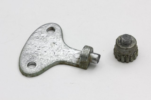
Looking at the damage, it was clear they forcefully tried to remove the nuts securing the mirror and it just snapped off. The other bracket on the opposite side broke off too, but at a different location. I’m no metallurgist but it looks like the part was made from cast iron or something, and therefore quite brittle. For years now I didn’t dare to dismantle the mirror for exactly this reason: the thumbnut loosens up till a certain point then refuse to go further, which is also why I left it in place. I have already removed everything I could for them – toothbrush holders, any hanging towels and racks. Anything else still left on the wall is obviously not removable, or I would have done so already. But these fuckers took it upon themselves to try to remove the mirror when I left them alone for an hour. To say I was very pissed is an understatement.
When they told me they broke the mirror, I thought they had shattered the mirror glass. I was at least a little hopeful when I saw they had placed the mirror under the sink. Still, I was at a loss of how to fix the mirror, until the idea of leveraging 3D printing hit me days later. I’ve known about it since the MakerBot days (and it was a hot topic at maker faires) but since I don’t have a 3D printer or easy access to one, it was just something I didn’t care too much about.
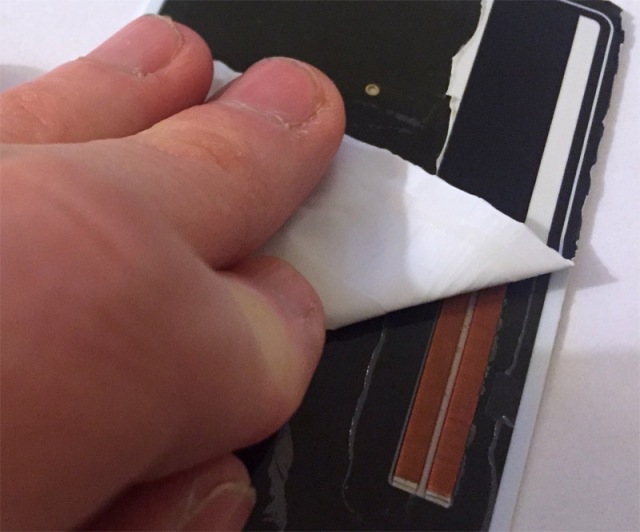
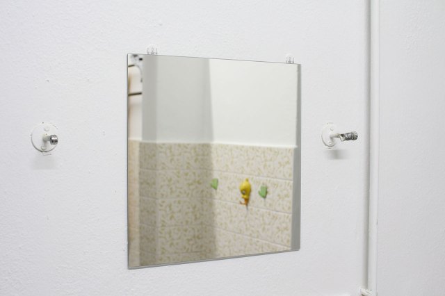
What is in its place now is a piece of IKEA BLODLÖNN, which I have used 3M Command strips to temporarily hold in place, while I tried to learn enough FreeCAD to design a replacement bracket. Buying IKEA was the cheapest option, and I had an inkling that learning FreeCAD from scratch was going to be a steep learning curve, so we needed something to use in the meantime (we kept looking up but finding ourselves staring at a blank wall). You can see the metal supports arms for the tilting mirror are left intact on the wall, but now painted white1.
Follow me as I detail how difficult it is for someone with zero experience like myself to learn FreeCAD, which hopefully inspires you not to give up, and the final results of my journey.