Testing the Shinyei PPD42NS

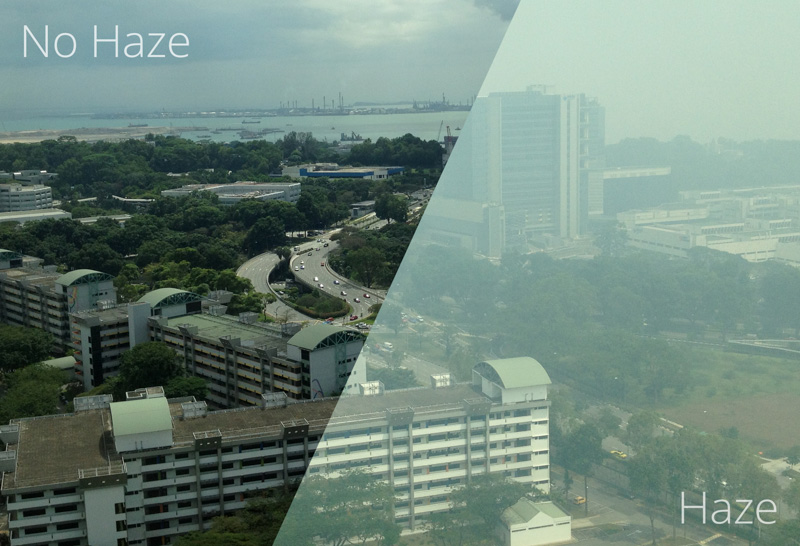
Around this time last month, the haze (or what some people call smog) here set a record high level for the Pollutant Standards Index (PSI). This is what it looked like outside:

haze vs no haze

As our National Environment Agency only published 3 hour PSI averages, I thought it would be good if we could get our own measurements. The PSI used here is somewhat like the Air Quality Index (AQI) used in the US, and is made up of 5 components:

  1. PM10 particulate matter
  2. sulphur dioxide (SO2)
  3. carbon monoxide (CO)
  4. nitrogen dioxide (NO2)
  5. ozone

Note that the AQI includes PM2.5 particulate matter whereas PSI does not. From what we can see, I would think that a major contributor to the PSI is particulate matter (PM).

I took a brief look at the projects such as the Air Quality Egg and PACMAN. They used either the Sharp GP2Y1010AU0F or the Shinyei PPD42NS. These sensors generally operate based on the light-scattering principle, by measuring the amount of light that is scattered by particles.

The PPD42NS

Chris Nafis has done a great job documenting the use of both the GP2Y1010AU0F and the PPD42NS, compared against a Dylos DC1100 air quality monitor. As the GP2Y1010AU0F requires a certain pulse waveform to be supplied to its LED pin, I would say that the PPD42NS is self-contained and thus much easier to hook up.

PPD42NS (front)

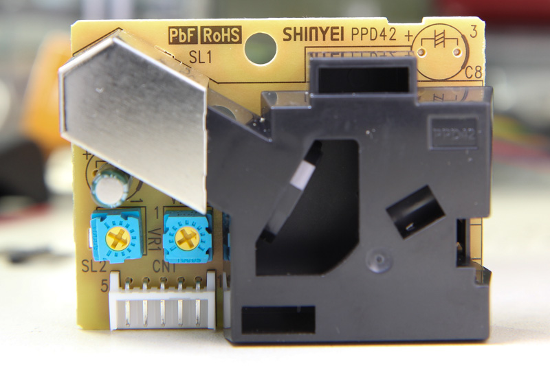
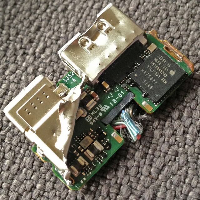
On the front, it has 2 pots labelled VR1 and VR3 that have been already factory-calibrated. The IR detector is covered under the metal can. Interestingly there’s a slot by the side labelled SL2 which is unused. If you’d like to see what’s under the hood, Chris opened up the black casing and posted a photo here.

PPD42NS PCB

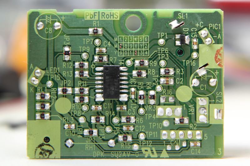
Looking at the date code grid on the PCB, the units look like they were manufactured in July 2012. The circuit consists largely of passives and an op-amp. RH1 is the resistor heater which, in theory, could be removed to save power if there was some other method of air circulation.

Continue reading

CY-20 Cheap Flash Teardown

Following up on my DIY slave flash project, I thought I’d get something more powerful than that tiny Xenon bulb. I bought the cheapest flash on DX.com – the CY-20. It has a considerably large bulb and as a plus, it has what looks like a tiny window on the front for automatic output control. The main reason for getting this was the 2.5mm jack on the back of the flash that allows it to be externally triggered.

retaining clips on the CY-20

Opening it was easy. Remove the 4 screws that secure the hotshoe mount and go round the casing to release the retaining clips. Surprise surprise, take a look at the sensing window.

CY-20 open, showing the decorative

Continue reading

Circular Layout ULP for Eagle

Some time last year, Mats Engstrom shared his PHP script for generating commands to move components in CadSoft Eagle to form a perfect circle. If you look at the screenshot, it’s mainly made up of MOVE and ROTATE commands – relatively easy.

Eagle has what it calls user language programs (ULPs) for doing some simple scripting with the ability to display a dialog for user input. I decided to try my hand at creating a ULP that creates these circular layouts. The main advantage of using a ULP is that it has access to your board layout, saving you from some typing. You can also easily iterate through different parameters quickly and without hassle.

I shall illustrate briefly how this circular layout ULP can be used for doing various kinds of layout, with help from some open-source projects with Eagle CAD files.

Ringo3 Clock

The most common use for a circular layout is in clocks. Conveniently, Mats has a project called Ringo3. For photos of the PCB and assembled clock, see this Dangerous Prototypes forum topic.

Delete the existing board (.brd) file to start with an empty PCB created from the schematic. We shall take (2.00, 1.60) to be the centre of the circle, as shown. Eagle 6 introduced a dimensioning tool, used here to show the radius of the circle (1.5″) – handy but not a must.

Ringo3 empty PCB layout

The circular layout ULP has 3 main sections: (i) parts selection, (ii) layout options, and (iii) circle centre point & radius. For parts, enter D for prefix and 1 to 60 and click the Filter button to select components D1 – D60 for layout. The handy table shows you the currently selected list of components. Enter 2 and 1.6 for the circle centre X, Y values that have been identified. The radius has been marked by the dimensioning tool as 1.5. The layout direction is “Clockwise” and we want to place D1 at the top “12 o’clock” position. Click the Do Layout button, and OK to start the layout.

Circular Layout Settings

You should see the components move into place as shown in the next figure.

Ringo3 PCB with laid out LEDs D1 - D60

If you make a mistake, you can always just hit Undo or hold down Ctrl+Z until all the components were back at their original positions.

Continue reading

Apple’s Lightning Digital AV Adapter

Recently, Panic noticed the odd output resolution and MPEG-like artifacts with the new Lightning digital AV adapter and decided to take a hacksaw to it. They found an ARM processor inside.

Lightning digital AV adapter

image credit: Panic blog

Shortly after, they received an anonymous comment that explains it all:

The reason why this adapter exists is because Lightning is simply not capable of streaming a “raw” HDMI signal across the cable. Lightning is a serial bus. There is no clever wire multiplexing involved. […] We did this to specifically shift the complexity of the “adapter” bit into the adapter itself, leaving the host hardware free of any concerns in regards to what was hanging off the other end of the Lightning cable.

This system essentially allows us to output to any device on the planet, irregardless of the endpoint bus (HDMI, DisplayPort, and any future inventions) by simply producing the relevant adapter that plugs into the Lightning port. Since the iOS device doesn’t care about the hardware hanging off the other end, you don’t need a new iPad or iPhone when a new A/V connector hits the market.

While I understand what they are trying to achieve, I think it’s sad that this new Lightning system can no longer carry the uncompressed HDMI output. Maybe they could have streamed the raw video output in a format close to what HDMI expects, then have the adapter add headers and trailers to the data, but that would still be tricky since the system needs to stop sending frames while the adapter is doing its work. And what about HDCP?

Just one of the many tradeoffs that engineers need to make.

Infrared Remote Control Protocols: Part 2

In the previous post, techniques on how to capture an IR remote signal were presented and the most reliable one was using the Arduino sketch. The captured signal was also analyzed, although we had much of our work already done for us.

In this concluding post, a remote control whose protocol is unknown will be captured and analyzed as a case study. Lastly, we will cover the re-transmission of the IR signal. The remote control in question is for my ceiling fan, KDK model M56SR. The remote also works for two other fan models M56QR and M11SU.

KDK remote control

Continue reading