A Quick Tour of Singapore Mini Maker Faire 2012

Closest to the door, MarketAsia Distributors were selling Make Magazines, including the latest Vol 30.

Singapore Robotic (sgBotic) was also there showing off their products. They were using what looks like the Sparkfun thermal printer to print discount codes from an Arduino. I asked them if the printer was for sale and they said maybe soon.

Renesas Electronics Singapore was also there, showing off their GR-Sakura board which they hope will replace the Arduino. It’s powered by the RX63N series, clocked at 96MHz. It’s definitely more powerful than the Arduino as it has native USB capability as well as Ethernet connectivity, which looks like it’s connected via an SMSC USB-to-Ethernet controller, just like the Raspberry Pi.

As you can see, the board layout looks exactly like an Arduino, and from the overview sheet that I got from the booth, the pins seem to match up. I did inquire at the booth, but the Renesas guy didn’t know if it was the same layout.

Stephan February shows off his aquaphonics setup, consisting of plants and fishes (in a barrel below) in a symbiotic ecosystem. The plants get their nutrients from the fish waste, and the waste is broken down before it get back into their tank. He has a larger set up at home and grows his own vegetables.

The Tangible Programming Toolkit is made up of these little cubes which can be easily programmed via a simple GUI. The “program” is uploaded via XBee into these cubes and they can interact with each other. Each cube consists of an XBee with an Arduino Pro Mini.

The Portabee is a lower-cost, foldable 3D printer, which itself uses 3D-printed parts. It uses polylactic acid (PLA) instead of ABS for printing. From what I understand, the board design has been tweaked by them.

I regret not staying longer, taking more photos and chatting with more of the makers that day. That’s all I have for my tour of the Singapore Maker Faire 2012.

There were a lot of booths I did not cover, such as the Dangerous Prototypes booth where they had their Bus Pirate and the Logic Sniffer on display, and there were also several robots for the RoboCup. I saw a tesla coil at Derek Low’s booth, but much to my disappointment he said it wasn’t working.

More coverage can be found on the Singapore Maker Faire Facebook page.
Infrared Remote Control Protocols: Part 1

As I was perusing the SB-Projects site on the different IR protocol formats, I decided to make a summary but later found out that it was a pretty standard thing, as documented by a Vishay document “Data Formats for IR Remote Control” (pdf).

The infrared remote control signals are layered on top of a carrier signal of 36 or 38kHz, therefore the signal can only be “on” or “off”. A transmission typically starts with an a burst (“on” state) that is used for the Automatic Gain Control (AGC) circuitry in the receiver, followed by the “off” state and the actual data transmission.

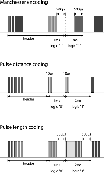
There are 3 basic types of data transmission formats, which are illustrated in the following diagram. Protocols can be based on these transmission formats, but need not necessarily conform to them.

Illustration of IR data transmission protocols: manchester encoding, pulse distance coding and pulse length coding.

So how do you know what your remote control uses? And how do you capture the sequence so that you can re-transmit it from an IR diode?

Continue reading

The Apple 30-pin Dock Connector

The 30-pin dock connector first appeared on the iPod 3G in 2003, and has been on all iPods, iPhones and iPads ever since, with the sole exception of the first generation iPod Shuffle. The first gen Shuffle looks like a thumbdrive (or what some would call a pen drive) and used a USB male connector, whereas the first and second generation iPods had a FireWire port at the top.

iPod Accessory Protocol

Since its introduction, Apple made several minor modifications to the electronics interface of the dock connector, but the physical connector itself remains unchanged. Collectively, this and the communications protocol is called the iPod Accessory Protocol (iAP).

Initially, they introduced different resistor values on the “accessory detect” pin when they allowed third-party companies to make docks and car adapters. At that time, the dock connector mainly had audio in and line out functionality (connected to the back of the docks), as well as a serial interface for remote control via the dock. The serial protocol was largely reverse-engineered by maushammer (website no longer accessible) and this guy here (I think he’s called Christoph but it’s not on that page). This was also used by car manufacturers to allow iPod playback control from buttons on the steering wheel.

When Apple released the iPod Video that was capable of playing videos in 2005, they added video out (composite and S-video), as well as an authentication chip to allow only authorized docks and cables to receive video out (including audio). Soon enough, China caught up with their release of “authorized” accessories, which contain the authentication chip that can be re-purposed for other use.

Authentication chip (image from thice.nl)

Presumably, that was also when they added USB support for iAP, which I’m pretty sure also requires an authentication chip. USB support would allow a host to communicate and control the iPod through a USB cable. My car stereo correctly recognizes the iPhone as an iPod over a USB cable.

The iPod Camera Connector was also introduced for the iPod Photo and iPod Video in 2005. This was a small “dongle” that has a dock connector on one end and a USB port on the other. Oddly, according to an Everymac article, later iPods released in 2006 do not support this accessory any more. It is unknown if they somehow switched the USB interface to host mode, or if they used a separate chip to emulate this.

In 2008, charging via FireWire was no longer supported with the introduction of the 2nd generation iPod Touch and 4th generation iPod Nano. The pins dedicated to FireWire in the dock connector are now unused.

Continue reading

DIY Optical Slave Flash

I found a couple of old disposable cameras in storage that I played around with 15 years ago, shorting the caps to make a loud bang, wiring up the flash trigger to a remote-controlled relay kit I had assembled. I thought I’d do something useful with them.

I decided to turn them into optical slave flashes, since on-camera flashes are not very flexible. I was thinking of a way to detect the camera flash so that the slave could be fired, maybe using an LDR with the ADC to detect an increase in light intensity? It turns out there’s an even easier way to do this – with an infrared sensor. Apparently when flash tubes are fired, they give off infrared which can be detected more reliably than light intensity changes. When I read about this, I tested it out with a simple Arduino sketch and it works as advertised.

Disposable cameras usually have metal contacts that are placed near the shutter mechanism. When the shutter opens, the contacts are closed and if the flash was charged it would fire. To control the flash firing, I replaced the contacts with an SCR.

Continue reading

Logic Analyzer Software Review

I was looking into the Openbench Logic Sniffer (OLS) client, an open source logic analyzer software to be used with the Logic Sniffer from Dangerous Prototypes and Gadget Factory, so I thought it might be worthwhile to look at other alternatives, including commercial products. In the next few posts, it will probably become obvious why I’m doing this.

Since I do not have any of the hardware, I must make it clear that I am only reviewing the software that is meant to be used with their analyzers. Good logic analyzer products will usually make their software available free, with either some demo files or a means to generate random or test waveforms.
Continue reading