ONV PD3401G PoE Splitter Teardown & Review

Continuing my PoE series, I bought the ONV PD3401G, an active PoE splitter that is capable of extracting up to 60W (24V @ 2.5A) from the PSE. It is housed in a small aluminum extruded case that can be DIN rail mounted. This splitter is comparatively low-cost, about US$35, and more importantly, is capable of passing through Gigabit.

ONV seems to be quite a reputable company, so I believe their products shouldn’t be too badly designed. This unit can also be easily purchased on Aliexpress without having to go through some obscure distributor.

ONV PoE splitter, side view

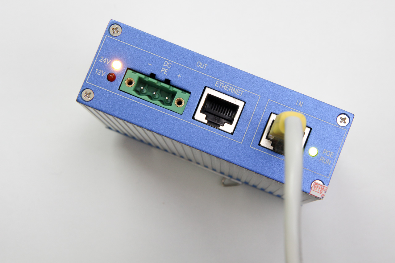
ONV PoE splitter, front view

Internally it uses the LT4275A (marking LTGBT) for PD interfacing. The A variant of this chip supports up to 90W of power. On the power supply side, it uses a NCP1034 synchronous buck converter. The NCP1034 is capable of handling up to 100V, which is more than sufficient for PoE.

Looking inside, the in/out Ethernet ports are connected via a transformer, in order extract power from the center taps of each pair. We can see that the PCB traces for the input port pairs are thicker to carry the higher currents. Large beefy diodes form rectifier bridges for the data pairs.

PCB, top side

Surrounding the input port on the underside, there are a lot of unpopulated components; those were supposed to offer input protection, probably using some TVS of some kind. these are marked RD1 ~ RD8, one for each Ethernet wire.

Continue reading

Extending ASUSWRT Functionality, Part 2

Following up from my earlier post, Asus has released faster and beefier routers. But perhaps the more important change here is that they have moved from MIPS in the RT-N56U to ARM in newer routers. I have also upgraded to the RT-AC68U for better reception and hopefully to fix the poor battery life experienced by my Android tablet.

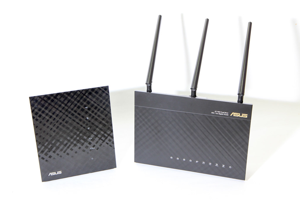
the Asus N56U and AC68U routers, side by side

After upgrading, I noticed that the method I described back then no longer works. Someone also noticed this, as they translated key portions of my post into Chinese, while pointing out some of the steps that didn’t work.

In this post, I’ll summarize the key changes required to get it working again.

Continue reading

PoE: Quick Guide & Cheap Hardware

I have been looking around for Power over Ethernet (PoE) devices to supply power to some networking hardware that will be located in a remote location, without a convenient power outlet. These networking hardware do not have built-in PoE support, so I have to find both an injector and a splitter device.

PoE is typically found on enterprise networking equipment, which usually means a higher price tag. Not wanting to spend a ton on PoE hardware, I did some research to understand what was required to make it work.

Hopefully this will help you understand PoE, how it works, and what to look out for when shopping for PoE hardware that are suitable for your needs.

PoE Quick Guide

Active vs Passive

Passive adapters are very simple, and you will see them mostly as an RJ45 socket with pigtails for power and Ethernet. These adapters do not contain or require any circuitry, which also explains why they are the more inexpensive option between the two.
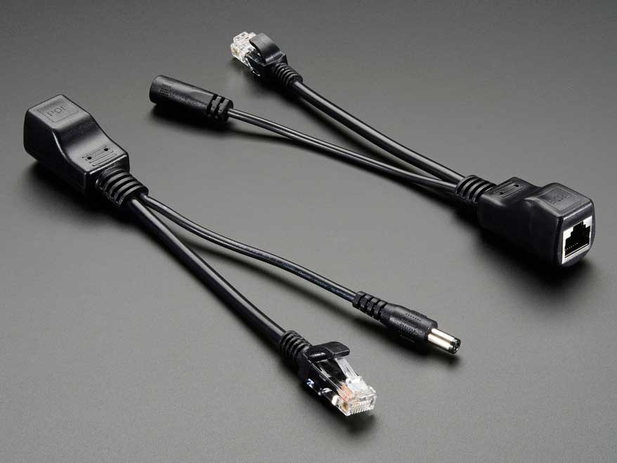
Photo of a passive PoE injector & splitter pair, sold on Adafruit

Active PoE (the real Power over Ethernet) on the other hand requires some negotiation between the two devices, called the PSE (power sourcing equipment) and the PD (powered device).

There are several PoE standards. 802.3af, 802.3at and the newer 802.3bt. The difference is mainly in the maximum power is made available to PDs:

  • 802.3af – 15.4W
  • 802.3at – 30W
  • 802.3bt – 60W to 100W

802.3bt was just ratified in the last year (2017). In the time span before the 802.3bt standards was ratified (~8 years!), some companies like Linear Technolgy & Cisco Systems took it upon themselves to find other means of carrying up to 60W. The result was LTPoE++ and UPOE, an evolution of the existing 802.3af/at standards, but may not be compatible with the final standard arrived at by committee.

Mode A or B

The Cat5 cable has 8 wires, forming 4 twisted pairs. For 10/100Mbps, only 2 pairs are used: pair 1/2 for Tx and pair 3/6 for Rx.

The modes refer to how power is delivered to the device:

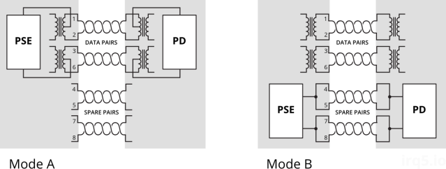
  • Mode A: pairs 1/2, 3/6
  • Mode B: pairs 4/5, 7/8

PoE mode A & B wiring diagram

Mode A uses the data pairs for power. This mode is well suited for very old cabling which didn’t connect all 4 pairs end-to-end. You might see some manufacturers calling this mode End-span wiring. To carry power over the same data cables, phantom power delivery is used (more on this later).

Mode B uses the unused (or spare) pairs for power. You might see this being referred to as Mid-span. This type of wiring is easier because it knows the pair is not carrying any data and thus can be wired directly.

Unlike mode A, mode B in this form cannot be used to carry power for Gigabit networks, because a Gigabit connection will require all 4 pairs for data transmission. Power must therefore be delivered via centre-tapped transformers, or what is known as phantom power. How this works is explained in a 1944 US Army video on telephone electronics.

Power Capacity

The committee decided that two pairs of Cat5 wire should only carry up to 30W of power; which two pairs will depend on whether mode A or B wiring is used.

For higher power capacity like 802.3bt (PoE++) or the non-standards-based UPOE and LTPoE++, the other 2 pairs will be paralleled up, making use of all 4 pairs to carry higher currents.
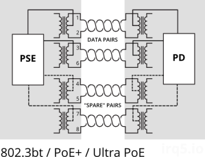
PoE wiring diagram for 4-pair based PoE

For Gigabit Ethernet (1000Mbps), because all 4 pairs are used to carry data, power (regardless of which pairs used) must be delivered via phantom power delivery.

Why use Active PoE?

In short, because it is safer.

It was designed with the consideration that not all network equipment can accept power, whether via the data pairs or spare pairs.

During the detection phase, the PSE will apply 2.7V to 10V to check for a known resistance. This voltage is low enogh and also for a brief period such that it wouldn’t matter if the device on the other end is shorted. A device that was not designed for PoE would thus never see any higher voltage beyond the detection phase.
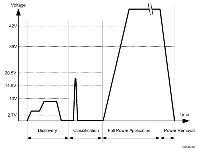
Graph depicting voltage vs time during various PoE phases

In contrast, passive PoE makes the full voltage and current available on the data/spare pairs. If the remote end is using a magnetics configuration that shorts out the centre taps, the 30W of power would just melt the port (one would assume).

Integrated PSE controller chipsets will also contain features like overcurrent protection, thermal cut-offs and surge protection, etc. which all contribute towards keeping your PDs safe from harm.

Finding Low-Cost PoE Hardware

It was quite a daunting task, trawling AliExpress for PoE injectors & splitters. The description or specifications for items are also not accurate; it’s like finding a USB cable listed as capable of carrying 2A when in fact it does not.

While passive injectors are the cheapest option, most of them are not meant for Gigabit Ethernet. Recall that Mode B wiring is the easiest and most low-cost method for building a passive device, and that is what you will mostly find. This wiring configuration does not pass through all 4 pairs and thus cannot be used for Gigabit.

Most active PoE splitters output 12V, or 5V via USB. This is largely due to the fact that these devices were meant for IP cameras, which operate at that voltage. If your target device uses a non-standard voltage, you will have difficulty finding a suitable (and yet low-cost) splitter.

Here’s a list of hardware I’ve found; which one is suitable for you depends on your requirements:

  • Do you need 1000Mbps, or just 10/100Mbps would suffice?
  • What voltage does your target device require?
  • How much power does it require? 13W, 30W?

Continue reading

Crypto-Erasing BitLocker Drives

These days with larger and larger drive capacities, erasing stored data takes longer and longer. Another problem is also the inability to do so when the time comes, due to bad sectors or hardware failures. Just because the data is not accessible by you does not mean that it is also inaccessible to someone else with the know-how.

Cryptographic erasure to the rescue!

Crypto erase simply erases the encryption key that is used to encrypt the data on your drive. This is the primary reason why I encrypt my drives.

Oddly, I have not found anyone talking about BitLocker crypto erasure or doing it. The closest I have seen is manage-bde -forcerecovery, which removes all TPM-related key protectors. This is briefly described in a TechNet article titled BitLocker™ Drive Encryption and Disk Sanitation.

But what if we are not running Windows? What if the disk is not a Windows boot drive that is protected by a TPM key protector?

In order to erase the (key) data, we first need to know how the data is stored on disk. For open-source FDE implementations, this is easy because the disk format is well-documented, but BitLocker is not exactly open.

BitLocker Disk Format

BitLocker was first introduced in Windows Vista and has gone through changes since then. Some changes were made to the format in Windows 7, but has largely remained unchanged through Windows 8 till 10.

For LUKS, it is simple – there is a LUKS header at the start of the disk, followed by the encrypted volume data. For BitLocker, it is slightly more involved, probably due to backward-compatible design considerations.

The header at the start of the partition is a valid boot sector (or boot block), so not all BitLocker information can be stored within. Instead, this volume header points to the FVE metadata block where most of the data is kept. In fact, there are 3 of these for redundancy. This metadata block is what holds all the key material.

The metadata blocks are spaced (almost) evenly apart, located near the start of the volume.

# blwipe -offset 0x2010000 bitlocker-2gb.vhd
metadata offset 0: 0x02100000
metadata offset 1: 0x100c8000
metadata offset 2: 0x1e08f000
metadata block 0 (size 65536): parsed OK
metadata block 1 (size 65536): parsed OK
metadata block 2 (size 65536): parsed OK

The first metadata block usually begins at 0x02100000. This illustration depicts the locations for a 2 GB volume:

Diagram of disk layout with FVE metadata blocks marked out

If there are 3 of these blocks, how do we know know which ones contain valid data?

Continue reading

Replacing a Linux RAID Drive

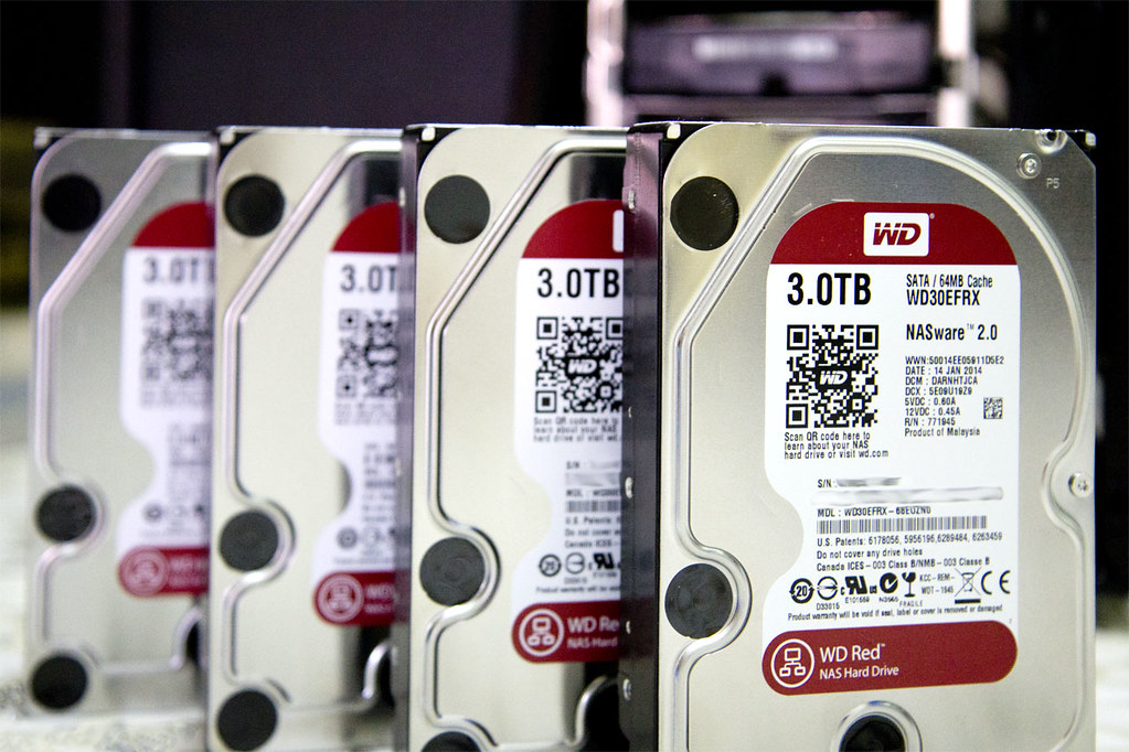
NAS drives

I have been running a software RAID array at home for some time now. It’s a single network storage where I consolidate all my files. I manage this array manually using the mdadm command. Some people choose to buy a NAS storage box which hides all of the implementation details behind a nice Web GUI, but it’s essentially the same thing under the hood.

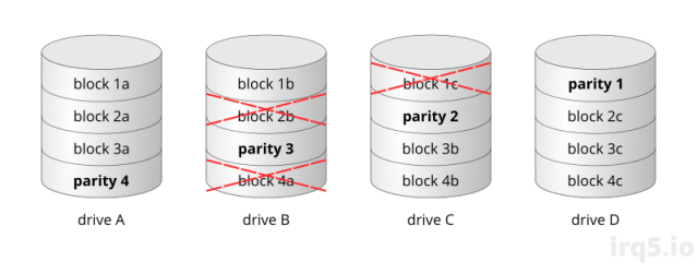
It operates with 4 drives using Linux software RAID 5, which means it can tolerate a single drive failure, but failures don’t always take out an entire drive. They usually manifest as bad sectors in a drive. As an illustration, the RAID 5 array below can still operate properly (meaning no data loss, yet) with bad sectors on two of its drives:

RAID 5 array with damaged blocks

As long as the other drives in the array doesn’t develop bad sectors in the same stripe, the data can still be reconstructed from the remaining good blocks. This means that you can somewhat leave the drive as it is for a period without replacement, but of course you are taking a risk.

I thought I’d share my experiences with drive replacements thus far.

Detecting Drive Problems

Most Linux distributions provide the raid-check script for periodic RAID scrubbing. This is basically a background cron job that tells the kernel to start checking the RAID array. For RHEL/CentOS systems, this should occur every weekend.

During this scrubbing process, all drives within the array are read and their parity blocks are computed, to ensure that everything tallies.

It is during this verification process that sometimes causes hard drive errors to show up. Typically when a drive encounters a problem during read, the hardware returns an error, which will then be logged by Linux. They can look like these:

ata3.00: exception Emask 0x0 SAct 0x0 SErr 0x0 action 0x0
ata3.00: irq_stat 0x40000001
ata3.00: failed command: READ DMA EXT
ata3.00: cmd 25/00:00:d8:10:27/00:02:05:00:00/e0 tag 8 dma 262144 in
         res 51/40:1f:b8:12:27/00:00:05:00:00/e0 Emask 0x9 (media error)
ata3.00: status: { DRDY ERR }
ata3.00: error: { UNC }
ata3.00: configured for UDMA/133
ata3: EH complete
 .
 . (repeats)
 .
sd 2:0:0:0: [sdc]  Result: hostbyte=DID_OK driverbyte=DRIVER_SENSE
sd 2:0:0:0: [sdc]  Sense Key : Medium Error [current] [descriptor]
Descriptor sense data with sense descriptors (in hex):
        72 03 11 04 00 00 00 0c 00 0a 80 00 00 00 00 00
        05 27 12 b8
sd 2:0:0:0: [sdc]  Add. Sense: Unrecovered read error - auto reallocate failed
sd 2:0:0:0: [sdc] CDB: Read(10): 28 00 05 27 10 d8 00 02 00 00
end_request: I/O error, dev sdc, sector 86446776

Continue reading