I found a couple of old disposable cameras in storage that I played around with 15 years ago, shorting the caps to make a loud bang, wiring up the flash trigger to a remote-controlled relay kit I had assembled. I thought I’d do something useful with them.
I decided to turn them into optical slave flashes, since on-camera flashes are not very flexible. I was thinking of a way to detect the camera flash so that the slave could be fired, maybe using an LDR with the ADC to detect an increase in light intensity? It turns out there’s an even easier way to do this – with an infrared sensor. Apparently when flash tubes are fired, they give off infrared which can be detected more reliably than light intensity changes. When I read about this, I tested it out with a simple Arduino sketch and it works as advertised.
Disposable cameras usually have metal contacts that are placed near the shutter mechanism. When the shutter opens, the contacts are closed and if the flash was charged it would fire. To control the flash firing, I replaced the contacts with an SCR.

I brought the SCR gate pin and +1.5V out onto a breadboard and prototyped a simple circuit with a IR-filtered phototransistor from my parts bin. Using an IR remote, I was able to trigger the flash. However when I used a camera to take a photo of it, it didn’t work – the flash in the photo didn’t have that bright burst of light.
I knew that red-eye reduction works by firing the flash prior to the actual exposure, but I had already disabled it. The flash was indeed triggered, but lengthening the exposure time to 1 second still captured nothing. I realized the problem when I saw the flash firing through the viewfinder just before the mirror flipped up on my SLR – it was firing too early.
Modern cameras will fire a brief flash pulse, called a pre-flash, for metering just before the actual exposure. This pre-flash is what triggers the slave. This simple passive circuit works perfectly when I disabled the pre-flash on my SLR by setting the flash to Manual, but the Panasonic LX3 has no manual flash setting. Since I wanted it to work with “normal” cameras, I had to ignore the pre-flash.
High Voltage Warning
Before working on such a project, you must know that the 1.5V goes through an inverter to produce 200 – 300V, which is then kept in a storage capacitor. Even if you remove the battery and the flash has been fired, there is still energy in the capacitor. Discharge it first before you attempt to work on the circuit board. Additionally, the capacitor is discharged into another transformer to generate a pulse of a few kilovolts.
I am in no way responsible for any injury or death that results from reading this post and/or trying to make your own. Please exercise caution and common sense.
Designing the Slave Trigger
Using a microcontroller would ensure a lower part count, but it meant that an additional power source was required as most microcontrollers require at least 1.8 to 2V. To keep it simple, I used a CR2032 coin cell, which I ripped out from an old motherboard along with its holder. I chose to use the ATtiny25 (which was supposed to be used for another project) because avrdude is so convenient.
I read that pre-flashes occur about 10ms or so before the actual flash, so the ATtiny looks out for a first flash and starts a timer. If a second flash occurs before the timer overflows, it fires the slave flash. The timer resets, either after sensing the second flash or after a timeout, and the cycle repeats. The firmware utilizes the power-down sleep mode when it is totally idling. The pre-flash would then wake the MCU to start the timer and enter idle sleep to keep the timer running. When the timer overflows, it is stopped and reset, and the MCU enters power-down sleep mode again.
I didn’t optimize the code too much because I might use the ATtiny4 or ATtiny9 in future. The 6-pin MCUs are really suited for this application because of its size (but the minimum voltage is still 1.8V).

You can see the slave flash in action here, lighting up the work area by bouncing light off a sheet of paper placed above – very nice illumination. Again, I used the Sparkfun FTDI breakout board to program the ATtiny25 in bitbang mode with avrdude (same method I used for the ATtiny10).
In its current form, it’s not really ideal for use so I had to build the circuit on prototyping board. Transferring the circuit onto the prototype board wasn’t without problems. I wasted quite a bit of time troubleshooting, and killed some components, but it worked out in the end.
I killed the ATtiny25 with ~300V from the camera somehow, so I’m now using an ATtiny85 as it is the only replacement I have. After the replacement, the MCU is able to flash an LED but still does not fire the flash. I know the storage capacitor was discharged because of that high-pitch charging whine. I traced the problem to the faulty SCR, which managed to discharge the capacitor but not fire the flash. Replacing the SCR solved the problem.
Here’s what it looks like now:

Improvements
If you’re worried about getting a jolt, you should use an opto-isolated triac to trigger the flash, which is what the SPOT project does. With the triac housed inside the camera, any wires coming out of it would be safe to touch. However, I would try to avoid a 3.5mm plug for any sort of high voltage – there’s a reason why they chose such a connector for the flash PC sync port.
Sadly the “charged” neon indicator no longer works on the cameras. Do neon bulbs have a short lifespan? Other improvements might be to change the inverter on the camera to get faster recycle times, as well as an automatic charging cutoff – right now the inverter keeps working, even after the capacitor has been fully charged.
Actually I’d like to buy a cheap flash with a much larger flash head and faster recycling time, and just build the optical trigger circuit for that.
If you are interested, Sam’s Strobe FAQ is a treasure trove of information on the topic.
Build It
Here’s the schematics and source code for the optical slave flash circuit.
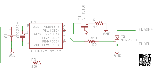
You may use an ATtiny25, 45 or 85 since the firmware doesn’t require any special features, and they are all pin-compatible. T1 is a SFH313FA (IR filtered phototransistor) which was left over from my university project, T2 is an MCR22-8 (SCR 600V), and the other parts are just resistors and an electrolytic capacitor.
#include <avr/io.h>
#include <avr/interrupt.h>
#include <avr/sleep.h>

#define _SEI() sei()
#define _CLI() cli()
#define _SLEEP() sleep_mode()
#define _NOP() do { __asm__ __volatile__ ("nop"); } while (0)

#define FLASH_PIN	PB3
#define SENSOR_PIN	PCINT2

// timer0 prescaler: CS02 | CS00 = clk/1024
#define TIMER1_CS	((1 << CS02) | (1 << CS00))

int main(void) {
	// setup ports
	DDRB |= (1 << FLASH_PIN);

	//DDRB  &= ~(1 << SENSOR_PIN);	// set as input
	PORTB |=  (1 << SENSOR_PIN);	// enable pullup

	// setup pin change interrupts
	GIMSK |= (1 << PCIE);
	PCMSK |= (1 << SENSOR_PIN);		// pin which IR sensor is on

	// enable timer0 overflow interrupt
	TIMSK |= (1 << TOIE0);

	// enable power down
	MCUCR |= (1 << SM1);

	// enable interrupts
	_SEI();

	// main loop is to sleep
	// sleep mode is controlled in interrupt handlers
	while (1) {
		_SLEEP();
	}
}

// handle IR sensor
ISR(PCINT0_vect) {
	_CLI();	// disable interrupts

	// if timer is inactive, start it
	if ((TCCR0B & 0b0111) == 0) {
		// reset and start timer0
		TCNT0 = 0;
		TCCR0B |= TIMER1_CS;

		MCUCR &= ~(1 << SM1);			// enable only idle sleep
	} else if (TCNT0 > 0x10) {
		// otherwise react only if the timer ran long enough

		TCCR0B &= ~TIMER1_CS;			// stop timer

		PORTB |= (1 << FLASH_PIN);		// fire flash

		TCNT0 = 0;
		MCUCR |= (1 << SM1);			// enable power-down sleep

		PORTB &= ~(1 << FLASH_PIN);		// unset flash pin
	}

	_SEI();	// re-enable interrupts
}

// handle pre-flash timeout
ISR(TIMER0_OVF_vect) {
	_CLI();
	TCCR0B &= ~TIMER1_CS;		// stop timer
	TCNT0 = 0;
	_SEI();
}

Hi Darell,
Could you please send me your email. I have a question regarding the optical slave flash.
Thanks 🙂
[…] up on my DIY slave flash project, I thought I’d get something more powerful than that tiny Xenon bulb. I bought the cheapest […]
Nice circuit and design. What are the clock fuses set to? I assume either 8MHz or 1MHZ internal oscillator.
The fuses are set to default – internal oscillator at 8MHz with a div-8 prescaler.
Thanks! That worked. I measured the current draw on your code. The chip enters deep sleep mode when first reset, with a current draw of a couple of microamps. After detecting a flash, it seems to be stuck in idle sleep with a milliamp of draw, which would impact battery life. I see in the code where you switch modes. Not sure why it is needed, but code stops working altogether if I comment out those lines! The switch back to deep sleep mode seems not to be working.
I found the issue! The ISR that handles the first flash timeout needs a statement to return the chip to deep sleep mode if the timer overflows on a single flash. Otherwise, the chip goes into idle sleep mode while waiting for the next event, drawing more current than needed. No clock is running as the ISR has shut it off, so deep sleep mode should be used.
The adjusted ISR is with the added line to set deep sleep mode is:
// handle pre-flash timeout
ISR(TIMER0_OVF_vect) {
_CLI(); //Disable interrupt
TCCR0B &= ~TIMER1_CS; // stop timer
TCNT0 = 0;
MCUCR |= (1 << SM1); // Re-enable power-down sleep
_SEI();
}
I tested it and the chip goes into deep sleep reliably, drawing only 1 or 2 microamps instead of 100 microamps or more.
I also noticed a very bright continuous light that forces the detection pin low will false-trigger the unit, as the code cannot distinguish between two short flashes and one very long flash that crosses the 10 millisecond timer boundary. The circuit never false triggers under normal room light, though, so this is not an issue. I have to shine a bright flashlight into the phototransistor to make it happen.
I also modified the code a bit to add a status LED that flashes when the circuit fires the flash. I also extended the flash trigger "on" time for use with a MOSFET flash trigger rather than the SCR. Works great. Thanks for the design.
Don
Ah, I missed out the OVF interrupt to restore MCUCR.
The problem with this circuit is that it can’t detect the flash if it is placed further away. It needs more analog circuitry around the photodiode to give the MCU a more usable signal.