In the previous post, techniques on how to capture an IR remote signal were presented and the most reliable one was using the Arduino sketch. The captured signal was also analyzed, although we had much of our work already done for us.
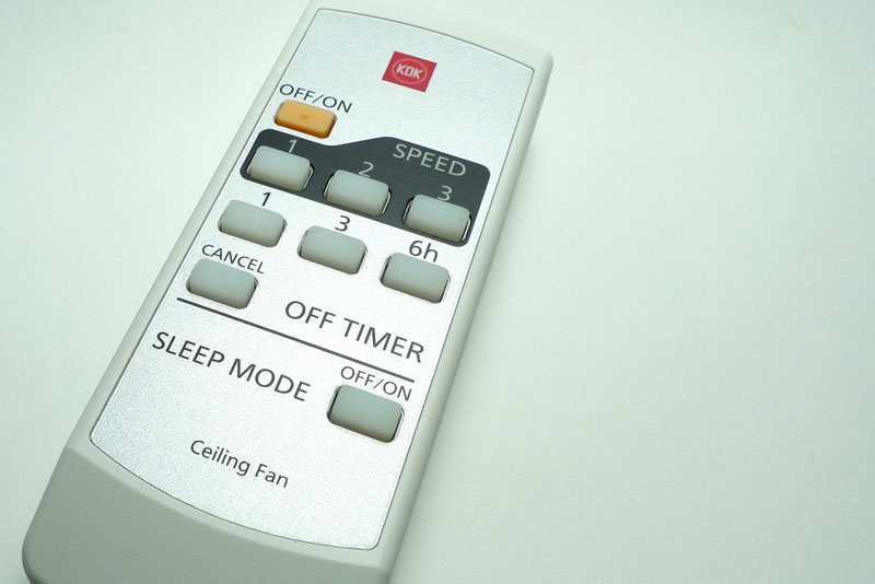
In this concluding post, a remote control whose protocol is unknown will be captured and analyzed as a case study. Lastly, we will cover the re-transmission of the IR signal. The remote control in question is for my ceiling fan, KDK model M56SR. The remote also works for two other fan models M56QR and M11SU.
The first step is to perform a capture of the remote signal to determine what are the pulse durations involved. For this, I pressed the On/Off button about 400 times, and obtained the following histograms. The value in bold is the chosen duration value that lies somewhere close to the middle of all the occurrences, indicated by the blue arrow. The middle value should be chosen since there will probably be some error when you try to reproduce the signal as well.
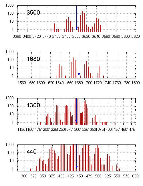
If we take a look at the raw values, it looks similar to the Apple Remote that we previously analyzed, except that the duration values are different. This protocol also seems to have 4 unique duration values, 2 of which are used in the header, and the other 2 are used in the payload. The signal even ends with a single “stop bit”.
3516	1664	500	372
468	1264	496	372
496	404	472	372
496	396	444	400
492	380	496	400
...
436	432	436	1296
436	440	436
Assuming that the protocols are similar, we begin decoding the signal by taking the pair (440, 440) as “0” and (440, 1300) as “1”. Each signal consists of 56 bits, as opposed to only 32 bits used by the Apple Remote. The signal for the “On/Off” button is decoded into the following 7 bytes (in hexadecimal):
02 20 d0 84 30 31 55
At this point, it looks quite good so we will proceed to decode the rest of the remote buttons in the same way:
02 20 d0 84 30 31 55– on/off02 20 d0 84 30 21 45– fan speed 102 20 d0 84 30 22 46– fan speed 202 20 d0 84 30 23 47– fan speed 302 20 d0 84 30 40 24– timer cancel02 20 d0 84 30 41 25– timer 1hr02 20 d0 84 30 43 27– timer 3hr02 20 d0 84 30 46 27– timer 6hr02 20 d0 84 30 4e 2a– sleep mode
This is typical of remote signals – they share most of the bytes and only a few bytes vary across the different signals (in this case it’s just the last 2 bytes). One way to tell that the decoded bytes are correct is the pattern formed by the second last byte. Let’s call this the “command byte”. For fan speeds 1, 2 and 3, the corresponding command bytes are 21, 22 and 23, and for the timer values 1hr, 3hr and 6hr, the command bytes are 41, 43 and 46, respectively. At this point, it makes you wonder what would happen if you send 42 or 44 instead.
Note that we were just lucky to have chosen to (correctly) interpret the pair (440, 440) as “0”. If we had did it the other way round, the bits would have all been inverted. This is where you have to start looking for patterns, or inverting the bits to make sure you’ve got it right, and this will take some time.
As for the last byte, notice that it varies with the command byte, but yet it doesn’t change between the timer 3hr and 6h command bytes. This should hint that the last byte is some type of checksum. Since remote control protocols are transmit-only, there needs to be a way for the receiver to make sure the signal is valid. To test this theory, I have printed the protocol bytes in binary, stacked on top of each other:
0x02 (00000010)
0x20 (00100000)
0xd0 (11010000)
0x84 (10000100)
0x30 (00110000)
0x31 (00110001)
0x55 (01010101) <-- checksum
Notice that if you do an exclusive-OR (XOR) on the highlighted bytes, you will get the same value as the last byte. Columns with a single 1 carry that 1 down to the result, whereas columns with two 1’s will result in a 0, and columns with three 1’s gives a 1. If you try to extend the XOR operation to include the first or second bytes, the result will no longer be correct.
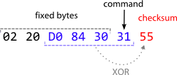
So at this point, the protocol has been pretty much reverse-engineered:
- Each command consists of 7 bytes, and the first 5 bytes are constant
- The 6th byte is the “command byte”
- The last byte is the checksum, computed by XOR-ing the 3rd to 6th bytes
This is illustrated in the following figure.
Armed with information about the protocol, we can begin writing the code to re-transmit this signal.
IR Transmission
As you may recall, each pulse that the IR is “on” is actually a 38kHz carrier signal. To emit this signal, I shall steal some code from Ken Sherrrif’s IR Arduino library to initialize Timer2 for PWM output. The IR LED needs to be connected to pin 3 on the Arduino. If you do not use an output transistor, you need to get quite close for the target device to pick up the IR signal.
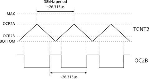
The initialization for Timer2 is as follows. Wave Generation Mode for Timer2 (WGM2) is set to mode 5 (phase-correct with OCR2A as TOP), and the prescaler is set to none. OCR2A is then set to the count for half the period of 38kHz (~13.158µs) at 16MHz, and OCR2B is set to one third that value, which would yield an approximate 33% duty cycle. The PWM output is enabled by setting the Compare Match output B (COM2B) bits to 2, which enables output during down-counting and clears during up-counting. The generated waveform and associated Timer2 values is shown in the figure below.
The functions to enable and disable the 38kHz IR signal are called mark() and space(), respectively. These functions are called by sendbyte(), which take a byte and starts transmitting from the least significant bit by calling mark() and space() with the durations measured earlier.
The demo sketch shown below delays 1 millisecond on reset and transmits the IR signal for On/Off. Note that the header and the “stop bit” must be transmitted as well. The sketch then goes into an endless loop, waiting for the next reset.
#define SYSCLOCK 16000000

// must use pin 3 for IR output

void setup() {
  pinMode(3, OUTPUT);
  digitalWrite(3, LOW); // When not sending PWM, we want it low

  // WGM2 = 101: phase-correct PWM with OCRA as top
  // CS2 = 000: no prescaling
  TCCR2A = _BV(WGM20);
  TCCR2B = _BV(WGM22) | _BV(CS20);

  // frequency and duty cycle
  int khz = 38;
  OCR2A = SYSCLOCK / 2 / khz / 1000;
  OCR2B = OCR2A / 3; // 33% duty cycle
}

inline void mark(int time) {
  TCCR2A |= _BV(COM2B1); // Enable pin 3 PWM output
  delayMicroseconds(time);
}

inline void space(int time) {
  TCCR2A &= ~(_BV(COM2B1)); // Disable pin 3 PWM output
  delayMicroseconds(time);
}

void sendbyte(unsigned char b) {
  int i;
  for (i = 0; i < 8; i++) {
    if (b & 1) {
      // one
      mark (440);
      space(1300);
    } else {
      // zero
      mark (440);
      space(440);
    }
    b >>= 1;
  }
}

void loop() {
  delayMicroseconds(1000);

  // header
  mark (3500);
  space(1700);

  sendbyte(0x02);
  sendbyte(0x20);
  sendbyte(0xd0);
  sendbyte(0x84);
  sendbyte(0x30);
  sendbyte(0x31);
  sendbyte(0x55);

  // stop
  mark (440);
  space(0);

  // sleep forever
  while (1);
}
Conclusion
This post concludes the series by reverse-engineering the IR signal used by the KDK M56SR remote control, as well as show an Arduino sketch that transmits these IR signals to emulate the remote.
As previously mentioned, if you are just re-transmitting the code, reverse-engineering is not necessary but it does satisfy my curiousity and it’s fun! However if you are building a receiver for this code, then reverse-engineering would definitely help. For this instance, we just need to match the first 5 bytes to the fixed pattern, record the command byte, and compute the XOR checksum to make sure the signal is valid. The receiver code will be much cleaner if you use a single switch-case block to handle the different button presses.
Hopefully you have found this walkthrough useful, whether you’re trying to reverse-engineer your own, or just happen have the same ceiling fan as me and want to know what IR protocol it uses.

Thank you for sharing! I’m trying to reverse-engineer an IR protocol with Arduino and this has definitely been an interesting reading.
Hi martip, glad you found it useful!
Hi, can you post the HEX codes or device decimal ir codes of this remote so as to program an IR blaster application on a phone?
Hi Haphy, the “HEX codes” depends on the program or device that is accepting these codes.
The remote data on this page provides you with the exact detail whether you want to reproduce the signal with an Arduino or to use an existing program or device that is capable of retransmitting the signal – you just need to get it in the right format. That is left as an exercise for the reader 🙂
Hi, i’ve a project to create a box spark core based, this the feature i need:
A contact sensor, when i push button my box must to be send an ir command to my air conditioner.
The box must be able to lear some code (tipycal On/Off) from air conditioner remote controller.
Someone can help me to find the right way?
Thanks
Hi
I catched this signal (vaccum remote) with mode2:
root@raspberrypi:/etc/lirc# mode2 -m -d /dev/lirc0
3467329
3062 992 1027 2994 991 3007
988 3005 2946 1032 998 3024
992 3004 992 21138 3055 1003
1026 2996 1000 2998 997 2995
2977 1002 1027 2995 990 3005
991 21137 3070 989 1017 3004
991 3005 991 3005 2978 1000
1019 3006 989 3004 992 21138
3056 999 1020 3003 993 3002
994 3001 2982 996 1026 2996
997 3000 995 21384 3062 996
1023 2999 996 3002 994 3000
2983 995 1023 2999 997 2999
996
My goal is to be able to reproduce it with irsend (raspberry pi)
i recorded with irrecord
$ irrecord -f -d /dev/lirc0 -f vaccum
the vaccum file is now like this:
begin remote
name vaccum
flags RAW_CODES|CONST_LENGTH
eps 30
aeps 100
gap 50192
begin raw_codes
name BTN_9
3057 992 1026 2995 1001 2995
1000 2995 2978 1003 1015 3002
994 3002 993
end raw_codes
end remote
i copied the vaccum file to lircd.conf and restart
$ /etc/init.d/lirc restart
unfortunatly nothing move when i do that:
irsend send_once vaccum BTN_9
My IRLed is working because i am able to control my TV with irrecord and irsend.
Can you help me ?
Regards
Hi, it seems from the
mode2output you provided, the IR signal was captured in the middle of transmission. It looks like the signal is a mix of 3000/1000 and the leader is 21,000. To understand what I’m talking about, refer to my Part 1 post. I haven’t actually usedirrecordbefore, but you should be able to runirrecordandmode2a few times, compare the values with those that I mentioned, then tweak the output file accordingly to make it work. Hope that helps.