I previously wrote about the hardware aspects of getting your code into an ATtiny10 some 7 years ago (wow that was realllyy a long time ago!).
Now, avrdude is at version 6.3 and the TPI bitbang implementation has already been integrated in. The upstream avr-gcc (and avr-libc) also have proper support for ATtiny10s now. These software components are bundled with most distributions, including the Arduino IDE, making it easily accessible for anyone. Previously a fully integrated and working toolchain only came from Atmel and it was behind a registration page.
The price of the ATtiny10 has also dropped by a lot. When I first bought this microcontroller in 2010, element14 carried it for $1.85 in single quantities. Now, they are only $0.56 each.
I thought I’d write up a short post about writing and compiling code for it.
Writing a simple program
Here is a simple program that blinks an LED connected to pin B2:
#include <util/delay.h>
#include <avr/io.h>

int main() {
    DDRB |= _BV(DDB2); // set as output

    while (1) {
        PORTB &= ~_BV(PORTB2); // turn off
        _delay_ms(1000);

        PORTB |= _BV(PORTB2); // turn on
        _delay_ms(1000);
    }

    return 0;
}
I typically don’t use any IDE. Instead, I prefer to manually build and link the object files; it’s really not that difficult. Compiling & linking are usually two separate steps, but for one-source-file projects, it can be done with a single avr-gcc command to get from C file to flash-able firmware:
avr-gcc -mmcu=attiny10 -DF_CPU=1000000 -g -Os test.c -o test.elf
You need to define the F_CPU because _delay_ms uses it to calibrate the delay time. By default, the ATtiny10 runs at a 1MHz clock speed (8MHz internal oscillator, with a divide-by-8 clock prescaler). The flag -Os optimizes for size and -g adds debugging information so that avr-objdump can intermix source lines and assembly code.
For larger microcontrollers, the following will not that crucial, but for something that has very limited flash space (like the ATtiny family), you should be wary of what your C code gets turned into.
You can view the generated assembly using avr-objdump:
avr-objdump -S test.elf
Specifying -S intermixes source lines with assembly, which can be a little confusing, but useful to help you understand how the compiler transformed your C code.
You can use avr-size on a compiled program to get an idea of how much space your program occupies. The -C flag produces an avr style report, which is easier to read. When you specify the type of microcontroller, it can additionally tell you how much flash space is remaining:
$ avr-size --mcu=attiny10 -C test.elf

AVR Memory Usage
----------------
Device: attiny10

Program:      70 bytes (6.8% Full)
(.text + .data + .bootloader)

Data:          0 bytes (0.0% Full)
(.data + .bss + .noinit)
Of course, doing all of this by hand repeatedly gets tedious after a while, so write a Makefile that automates this.
Using this simple Makefile, you can build the test.elf file by just typing make, or make all. The Makefile uses the normal two-step compile & link, but compilation (from .c to .o) is handled by an implicit rule, so you don’t see it listed in the Makefile.
If you are using Windows (and the Arduino IDE package), you need to make sure that avr-gcc is in your PATH by calling set like this:
set PATH=%PATH%;C:\arduino-1.8.3\hardware\tools\avr\bin
Uploading via avrdude is not covered by the Makefile, but you can easily add it in yourself. I got some inspiration from here: http://joost.damad.be/2014/01/programming-attiny10-in-linux.html
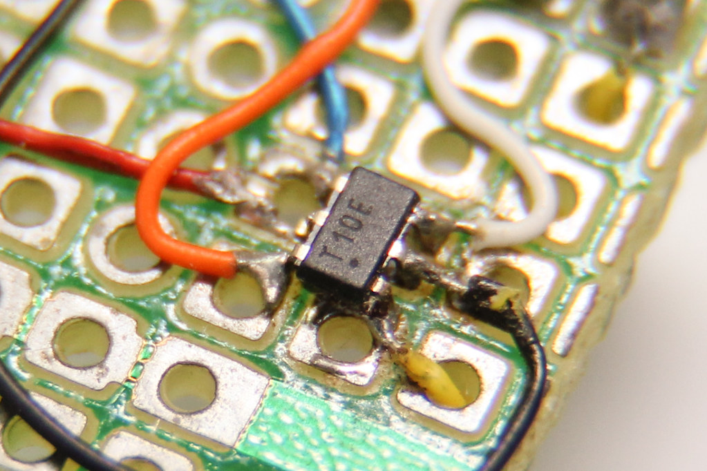
Programming the Chip
You can program an ATtiny10 with almost nothing but the chip and an FTDI serial converter. Remember to edit your avrdude.conf to include modify a dasa variant that has tilde (~) signs on all pins.
Previously, programming with avrdude required that you use a .hex file, but now avrdude can directly reads ELF files, so that conversion step is no longer necessary.
avrdude -C ..\etc\avrdude.conf -c dasaftdi -P COM5 -p t10 -U flash:w:test.elf
During the development process, you will be doing this very often. The uploading time is one of the easiest item to reduce. You can achieve this by using a dedicated programmer, such as the USBasp (or a Chinese clone).
Depicted here is the amount of time you can save when using a dedicated programmer:
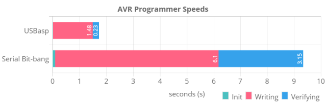
Comparing the different programmers, USBasp takes under 2 seconds for a programming cycle, whereas serial bit-banging took more than 9 seconds for the same firmware 1.
This should help to reduce the debug-edit-compile-upload cycle time by a lot.
Pinout
As the ATtiny family speaks TPI instead of the usual serial protocol, a single pin is used for both MISO and MOSI. For the case of the USBasp, you will need to connect MOSI to TPIDATA.
However, looking at the 6-pin ISP pinouts and Atmel’s recommended TPI pinout, it seems logical to use the pin connected to MISO (not MOSI) for TPIDATA instead. To resolve this conflict, I decided to use the more “standard” pinout, adopting what Atmel uses.
You will need to modify the USBasp source code in tpi.S to use pin B4 for both in and out. Pin B4 is connected to MISO:
#define TPI_DATAOUT_PORT PORTB
#define TPI_DATAOUT_DDR DDRB
#define TPI_DATAOUT_BIT 3      // <-- change this to 4
#ifdef TPI_WITH_OPTO
  .
  .
#else
#    define TPI_DATAIN_PIN PINB
#    define TPI_DATAIN_BIT 3   // <-- change this to 4
#endif
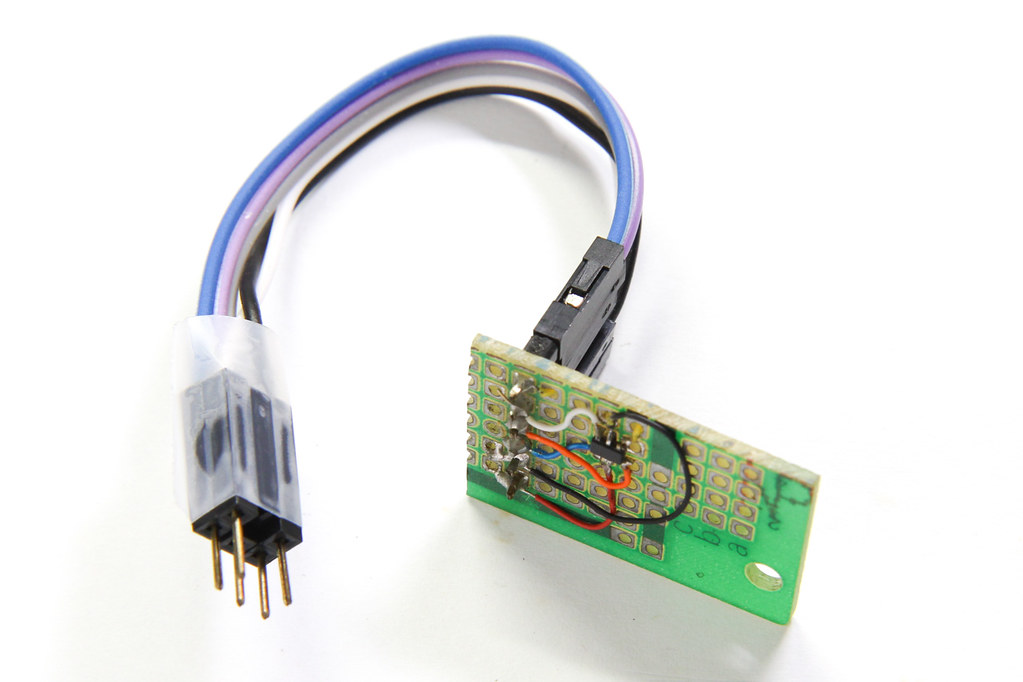
Following this standard pinout, I made a cable that plugs into the ATtiny10 protoype board to program with a USBasp programmer. And yes, this prototype board you see here is the same one I made 7 years ago.
C vs Assembly
The ATtiny10 has 1024 bytes of flash. With each instruction taking up 16 bits (2 bytes), you have about 512 instruction words available. Depending on how much functionality you are squeezing into your microcontroller, you may be struggling to get all your code to fit.
Writing in assembly gives you full control over these 512 words, but it also means slightly lesser readability (some people may disagree with me on this). That is why I usually prefer writing C.
But there are times when avr-gcc fails you. One of these instances is when creating loops.
In a typical example, supposing we want to create a “wave” that sweeps across PORTB which is all connected to LEDs. The C code would be like so:
void sweep() {
    unsigned char mask = 1<<7;
    while (mask) {
        PORTB = mask;
        mask >>= 1;
    }
}
You would imagine that the generated assembly is relatively straightforward, but in reality the generated code looks convoluted:
00000028 <sweep>:
void sweep() {
  28: 48 e0     ldi   r20, 0x08   ; 8  <-- WHAT'S THIS?
  2a: 50 e0     ldi   r21, 0x00   ; 0  <-- AND THIS??
        unsigned char mask = 1<<7;
  2c: 60 e8     ldi   r22, 0x80   ; 128
        while (mask) {
                PORTB = mask;
  2e: 62 b9     out   0x02, r22   ; 2
                mask >>= 1;
  30: 66 95     lsr   r22
  32: 41 50     subi  r20, 0x01   ; 1  <-- DEC
  34: 51 0b     sbc   r21, r17    ;    <-- CHECK END
        while (mask) {
  36: d9 f7     brne  .-10        ; 0x2e <sweep+0x6>
        }
}
  38: 08 95     ret
Notice here that GCC has decided to add a loop counter r20 set to 8, r21 as some kind of indicator when the loop has ended, plus the associated instructions to manipulate both r20 and r21. Why on Earth would a counter be necessary when the mask itself can be used to determine the end of the loop??
This issue is not only limited to the AVR architecture, but is also present in code emitted for the x86:
You can play around with this Compiler Explorer snippet here.
It turns out that this is the result of one stage of GCC optimization, which is controlled via the flag tree-loop-ivcanon, described in GCC optimization options as:
-ftree-loop-ivcanon
Create a canonical counter for number of iterations in loops for which determining number of iterations requires complicated analysis. Later optimizations then may determine the number easily. Useful especially in connection with unrolling.
The problem is, after adding this counter, the later “optimization” stages never happen and it is left in there, consuming two registers and several instructions for loading the counter, decrementing it, and checking it.
Disabling this optimization (by prefixing “no-“) will remove this canonical counter:
avr-gcc -mmcu=attiny10 -Os -fno-tree-loop-ivcanon -g test.c
The generated assembly code will now be exactly as we expect: r20 is the mask, which is sent out and also right-shifted. The end-of-loop condition is checked by inspecting the Zero flag immediately after, using the BRNE instruction.
4 simple assembly instructions:
00000028 <sweep>:
void sweep() {
        unsigned char mask = 1<<7;
  28: 40 e8     ldi   r20, 0x80   ; 128
        while (mask) {
                PORTB = mask;
  2a: 42 b9     out   0x02, r20   ; 2
                mask >>= 1;
  2c: 46 95     lsr   r20
        while (mask) {
  2e: e9 f7     brne  .-6         ; 0x2a <sweep+0x2>
        }
}
  30: 08 95     ret
Initially I worked around it using asm volatile directives (so GCC would never realise it’s actually a loop), but thanks to this AVR Freaks thread, I finally found out why GCC was doing this and how to disable it.
While these instructions may not account for much, they will add up when you are pressed for flash space and instruction cycle count when the clock speed is reduced.
When generating code for the ATtiny10, you should verify the generated assembly for such weird artifacts.
Summary
You can program an ATtiny10 with just the chip and a USB-to-serial converter. The compiler and tools are conveniently available with the Arduino IDE download.
If you prefer to write in C like me, you will need to ensure that the C compiler (avr-gcc) produces reasonably compact code. However, if you need to squeeze every byte and cycle out of the microcontroller, then you are better off just using assembly.
There are more avr-gcc “workarounds” that are required if you want more low-level control over the emitted code. I will discuss those in a future post.
- During testing, the serial bit-banging on Linux was oddly very slow, compared to Windows. On Linux, bit-banging took 135 seconds, 14x longer than the numbers presented here. ↩

[…] dado bastante juego para algunos en la comunidad maker. Hay varios artículos donde hablan de cómo desarrollar software para él, o donde han creado un tipo de firmware para un adaptador USB-TTL, y lo que mejor pinta tenía: un […]
Dear Darrell,
after reading your article on the very interesting ATTyny10, I am reminded of the years when I was programming an Intel 8008 with binary code, namely UNI and ZERI. (BHHHHLLLLF) One of my first programs was the one that allowed me to program 8008 in hexadecimal code (00 … FF).
Of course it was nice to have managed to simplify the programming, but even more wonderful was to see that I had managed (I was about 20 years old) to understand how the CPU, its registers, the other few resources on the programmer board for EPROM 1702 worked.
With programming in C or any language other than assembler, understanding how a CPU / MCU works is a part that gets very neglected.
In my opinion it’s a shame, because getting to know the link between the instructions and the internal parts that execute them is a very … “intriguing” part.
However, there is a risk of writing code for itself, sometimes hard to read and not always understandable.
My opinion is that with any language you aim at the result, while with the Assembler, which allows you to deepen down to the smallest details the ‘core’ you use, you risk losing sight of the final purpose and stubbornly on improvement and on abbreviation of the code, often at the expense of readability.
Whatever the pros and cons of these two ways are, I really appreciate articles like yours, I who am not a programmer, but let’s put it this way: I can program (not so well).
I say this so that it is clear that my words do not come from a ‘chair’, but from the back desk of the class.
I also want to add that the use of Assembler is not at all ‘advocated’ by the manufacturers. The result is that practically anyone can be able to program Arduino in “C” with the IDE (even me), but very few of us would be able to code a Blink using the Assembler.
Perhaps it is better this way, because in this way the door to the use of Arduino is open to everyone, both experts and newbies.
The Attiny10 seems to me, however, such a small MCU and suitable for ‘local’ functions for which the use of the Assembler could just be suitable or necessary.
So I congratulate you for your attention and for sharing your first observations and example applications.
Umberto
Am happy to read this awesome details on the Atiny10 IC.
Can someone please help me write
and send me a code that will enable the Atiny10 IC with this parameters and functions:
1. There’s an input momentary push button that is normally low.
2. There are two output LEDs let’s say green & blue which are also normally low or off.
3. When the button is pressed and release (goes high & low) the green LED first comes on for 2ms and goes off and then the blue LED comes on and goes off for also 2ms.
It should only run this function when the button is pressed and release. Please Contact me on WhatsApp if you can help 🤞+232 73 660 300